Nicholas Wright, EMC Partner AG, Laufen, Switzerland
Many disturbance sources can affect the correct functioning and therefore the safety of an aircraft. The latest commercial airliner designs include many technological changes that have necessitated a review of avionic system test requirements.
The trend today is to move toward structures made from Carbon Fiber Reinforced Plastic (CFRP) materials that offer all the strength of previous materials but with a significant saving in weight. The last few decades have seen increasing amounts of composite material used in aircraft construction, culminating in the latest designs from Airbus (A350) and Boeing (787). The latter includes over 50 percent CFRP materials.
In parallel the type and amount of electrical and electronic systems used has also increased dramatically. Some of the latest systems relying on variable frequency power and electrical systems for everything from the galley coffee machine to replacing traditional hydraulic control of the flying surfaces.
The requirement RTCA DO-160 and EUROCAE ED-14 embody many of the tests to be performed on commercial aircraft. Both documents are in fact published under an agreement between the RTCA, EUROCAE and the Society of Aerospace Engineers so that the content is identical.
All parts of DO-160 are equally important in their own right, but sections 22 and 17 are the focus for this discussion.
Section 22 discusses test requirements for indirect lightning testing of equipment mounted within an aircraft.
Latest generation aircraft require tests to the avionics equipment for which no experience existed. The responsibility is very much on the aircraft manufacturer to ensure that appropriate testing is performed. DO-160 / ED-14 remains the base for these tests, but separate standards are emerging for specific aircraft types with requirements to take account of construction, materials and amount of electronics.
INDIRECT LIGHTNING REQUIREMENTS
DO-160 / ED-14 section 22 defines a series of waveforms that represent impulse energy entering an aircraft and being induced into cable bundles within the structure. This can occur through resistive coupling or via induced E and H fields. Based on many decades of experience, six waveforms have been defined and are applied as damage assessment (PIN Injection) with fixed test system impedances or cable and ground injection disturbance (Single Stroke, Multiple Stroke & Multiple Burst) tests.

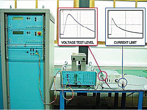
Cable bundle and ground injection tests specify a Test level (voltage of current) that should be achieved in the cable. This is coupled with a Limit level for either current or voltage. Waveforms are defined as having a predominately voltage form (WF2, 3, 4), current form (WF1, 3, 5A, 5B, 6) or a hybrid form (WF3). This latter can be defined in terms of either voltage or current.
There is no definition of test equipment impedance and the cable bundle impedance can have a significant influence on the test result.
To take account of changes in designs, aircraft manufacturers are basing their requirements on the principles in DO-160 but with some deviations.
WHAT DOES THIS MEAN FOR THE TEST EQUIPMENT AND THE TEST ENGINEER?
The DO-160 / ED-14 method requires constant monitoring of the impulses as the test signal is increased to the desired level. This is labour intensive and there is a risk that the cable impedance could prevent either the TEST or LIMIT level from being reached.
This situation requires a further test process and much more time. As these test types can already run for many days or even weeks, a further extension is undesirable.
Boeing test requirements set a Voltage level that should be reached in the cable, even if it means exceeding the current limit. This is still dependant on the cable impedance and may necessitate changing test equipment.
Airbus has arrived at a solution that is independent of cable impedance and in fact in line with most international impulse standards. The test system (generator, coupler and cables) is calibrated with fixed impedance as for PIN injection. After calibration, the test can be performed without monitoring impulse levels in the cable bundle.
A hybrid generator is a circuit design where the dynamic behavior is well known. The impulse waveform is specified in open circuit and again in short circuit. The advantage of this design is that independent of the load impedance (e.g. cable length, aluminium or carbon fibre structure ) the test results are repeatable and comparable. A hybrid solution is the only generator design that gives comparable test results over the complete EUT load range.
VOLTAGE SPIKE REQUIREMENTS
The DO-160 / ED-14 section 17 specifies requirements for voltage spikes in an aircraft power system. There have always been voltage spikes transmitted around system cabling in aircraft. In modern times, increasing complexity of electronic systems and the advent of full computer control of platforms has meant that voltage spikes need to be addressed at a whole different level to the past. Aircraft contain many sources that can „generate“ voltage spikes. The most likely source of voltage spikes are electric motors. All motors are inductors fitted in the power line. Energy is stored in the inductors magnetic field and when power is removed, is released as a spike with amplitude proportional to the inductor and therefore the motor size. In modern platforms there is a tendency to add more and more motors to automate certain functions. Aircraft have huge motors for flap and landing gear actuation. Because of the motor size, spikes can attain many times the nominal voltage level.
The phenomenon is fairly well known and many standards already exist, however, with the increasing technological challenges, existing ideas need to be challenged and revised where necessary. In particular the use of “fly-by-wire” technology requires a new level of immunity to voltage spikes to ensure aircraft safety.

REQUIREMENTS
DO-160 and ED-14 are identical and in section 17 address the voltage spike test requirements. The “classic” 2/10us impulse is used with a generator impedance of 50ohm to test AC and DC systems.
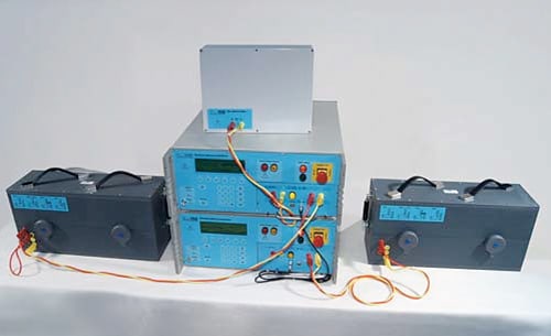
The latest edition of Airbus ABD0100.1.8 specifies testing requirements for the A350XWB aircraft. It is tailored specifically to include the experience gained by Airbus over many decades. The voltage spike tests included in this document, were originally proposed as specification AMD-24 C intended for the A400M military transport aircraft and A380 double decker. Based on the 2/10us impulse, this requirement adds a further 4 waveforms. The 2/50us, 2/100us, 2/200us and 2/400us. As pulse width increases, the test amplitude reduces. The intent is to inject higher energy levels into EUT cables, thus improving on the basic DO160/ED14 requirements. In order to achieve this aim, the generator impedance is reduced to 5ohm for all pulses except the 2/10us, this remains at 50ohm. There is a logical explanation for reducing the impedance. Power supplies tend to have very low impedances, so to transfer maximum energy from the generator into the cable the two should, ideally, be matched.

The longer impulses generate more energy at lower frequencies. A generator with high output impedance feeding a low impedance load will burn energy internally rather than transfer it to the load. The 2µs rise-time generates frequencies (at the 3dB point) of approximately 200kHz, so the majority of the energy is at lower frequencies.
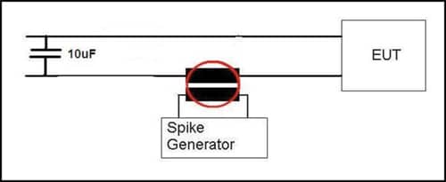
In all cases, DO-160, ED-14 and ABD0100.1.8, specify injection on cable bundles only. The preferred application method in all cases is SERIAL injection. This requires the impulse to be coupled into the EUT cable bundle using an inductive coupling clamp. Serial injection is most widely used due to the non-intrusive nature of the coupling. The type of coupler used must have the correct bandwidth to accurately transmit the impulse and not saturate when AC or DC power from the EUT is passed through it.


For power line coupling, there would be a tendency for impulse energy to flow into the low impedance power supply rather than the EUT. This is often overlooked but is simply addressed by inclusion of a 10µF capacitor fitted between phase and neutral or phase to phase for 3-phase supplies. This adds a high impedance block for the impulse energy, directing it to the EUT.
A common thread running through the various standards is the need to superimpose the impulse on all lines simultaneously. What does this mean? Should every cable attached to an EUT be subjected to the impulse at the same time, or does this requirement refer to a all the wires in a single cable bundle. The diagram in DO160 / EUROCAE which shows the testing one cable at a time.
However, ABD0100.1.8 does request SIMULTANEOUS testing on ALL CABLES containing power lines connected to any one EUT. This is logical as voltage spikes circulating in a system will impinge on all power interfaces simultaneously.
CONCLUSION
Safety of airliners and the traveling public is paramount. To maintain the current high standard as technology evolves, there is a need to re-think test requirements.
ABOUT THE AUTHOR
Nicholas Wright was educated at Worcester College, England. He has worked on military projects for the UK M.O.D., Marconi and GEC Avionics. Moving into the field of EMC, he has held posts as product manager and regional sales manager, culminating in his current position as international sales manager for EMC Partner based in Switzerland.


