By Kenneth Wyatt
Wyatt Technical Services LLC
Those of us who are either in-house or independent EMC consultants can benefit greatly by assembling our own EMI troubleshooting kit. I’ve depended on my own kit for several years and it has proven not only valuable, but depicts a sense of professionalism in dealing with your own product development engineers, their managers, or your clients, as the case may be. Mine is designed around a Pelican 1514 roller case (http://www.pelican.com) that includes a padded divider, so it is easy to transport to the area needed. You’ll also want to order the optional lid organizer, model 1519, for carrying extra tools, cables, and other small parts. See Figure 1.
This article will summarize what I’ve included in my own kit, and because everyone’s needs might be a little different, you’ll want to use this information as a guide. Feel free to add or subtract tools and test equipment as desired. You should expect to spend about $3k to $5k for the complete kit, depending on whether you make a lot of DIY probes or buy commercial, but this price range includes a spectrum analyzer.
I’ll list just the most important items for assessing radiated emissions in Part 1. You’ll be able to download Part 2 at the end of this article, which will include additional items required for assessing various immunity tests, along with many other useful tools and equipment. Some of this information is based on the book, EMI Troubleshooting Cookbook for Product Designers[1], by Patrick André and Kenneth Wyatt, with foreword by Henry Ott.
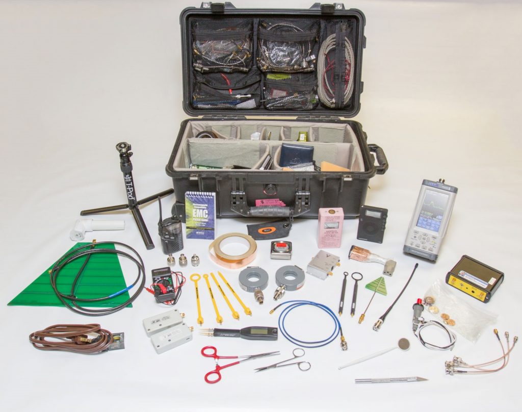
Figure 1 – Troubleshooting kit with most of the major components shown. The spectrum analyzer is the Thurlby Thandar model PSA6005 and tunes from 10 MHz to 6 GHz. Everything fits inside a Pelican 1514 roller transit case. The contents are described in Part 1 and Part 2 of this article.
Spectrum Analyzers
You’re probably wondering about the spectrum analyzer, so we’ll start with that first. The spectrum analyzer is the one piece of gear that’s essential for EMI troubleshooting, but has traditionally been the most expensive item in anyone’s kit. Many smaller or mid-sized companies may not have the budget to purchase a lab quality analyzer, which can start at a base price of $10k, or more. While you may find older used spectrum analyzers on sites, such as eBay or from used equipment dealers, several manufacturers are now making lower cost quality instruments that are perfectly adequate for troubleshooting and pre-compliance work. I’ve listed several instruments from which to choose – in categories, good, better, and best.
GOOD – I’ve run into a very low cost spectrum analyzer solution; the Triarchy Technologies (http://triarchytech.com) USB-controlled spectrum analyzer, which is about the size of a large thumb drive (Figure 2). Triarchy makes several models covering up to 12 GHz, but their Model TSA6G1 covers most of the commercial frequency range of 1 MHz to 6.15 GHz, can measure signals from -110 to +30 dBm, and costs just $629 through their eBay store or through their North American distributor, Saelig Electronics (http://www.saelig.com). The unit comes with Windows PC software and works perfectly well for troubleshooting. I wouldn’t necessarily use it for pre-compliance testing, but it should still provide a good enough indication as to whether you’re in the ballpark of passing or failing.
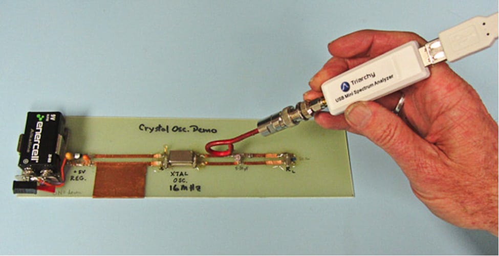
Figure 2 – Here’s an example of a low cost USB powered spectrum analyzer. This one is made by Triarchy Technologies and is sensitive enough for general EMI troubleshooting. The model TSA6G1 tunes from 1 MHz to 6.15 GHz.
BETTER -You may want to consider a better quality analyzer. I’ve been using the Thurlby Thander (TTi) PSA2702T (1 MHz to 2.7 GHz handheld, at $1695) for several years now (Figure 3) and recently upgraded to the model PSA6005. TTi is a British company (http://www.aimtti.com in the UK and http://www.aimtti.us in the U.S.), well known for their lines of test and measurement equipment. Newark (http://www.newark.com) and Saelig Electronics (http://www.saelig.com) are the North American distributors. Many other independent consultants are also using this one. It’s truly handheld and will easily fit into the recommended transit case. TTi also sells a similar handheld model PSA6005 that tunes from 10 MHz to 6 GHz and costs about $2,700.
These analyzers offer most of the usual settings for resolution bandwidth, frequency setting, saving/recall of instrument setups, different detectors, averaging, and max hold. The controls are all laid out at the bottom of the screen in a hierarchical fashion top to bottom. They also include two cursors, which can read out both frequency and amplitude simultaneously. There is also USB connectivity for control by free PC software. Battery life is very good at four to six hours. I can plug in a near field probe directly to the RF input and use the entire unit to quickly evaluate a large system for EMI issues.
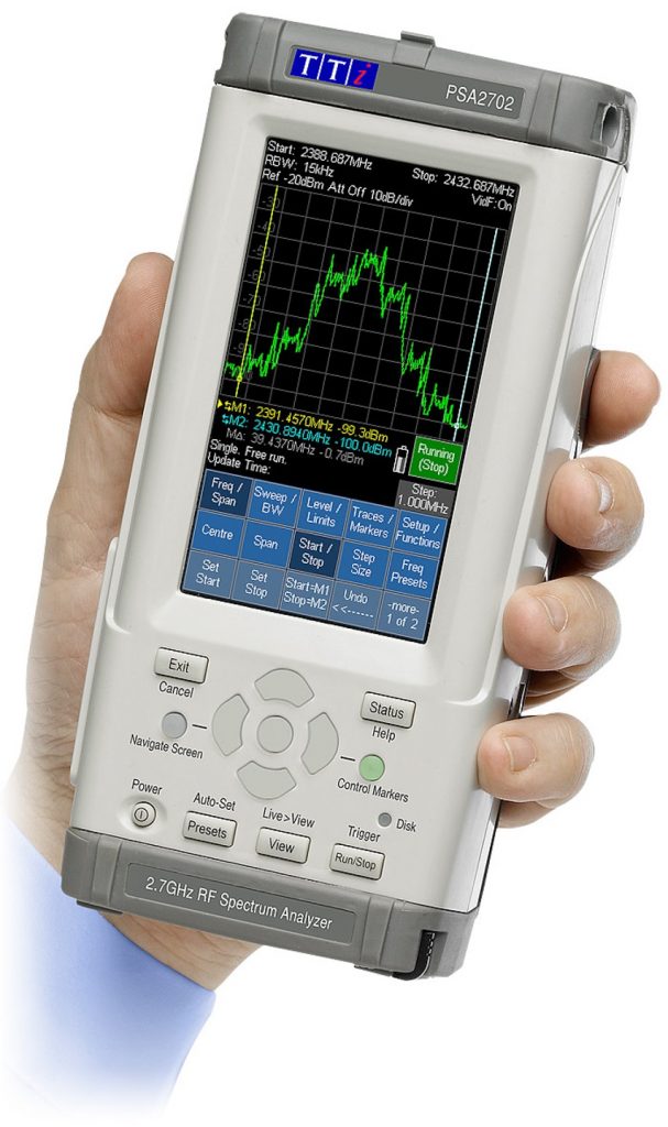
Figure 3 – The Thurlby Thandar PSA2702T is an affordable portable spectrum analyzer that covers 1 MHz to 2.7 GHz. The cost is just $1,695 from Saelig or Newark Electronics (Photo, courtesy Thurlby Thandar Instruments).
BEST – There are several affordable choices of quality bench top analyzers. My two favorites include the Rigol DSA815 (Figure 4) and Siglent SSA3000X-series (Figure 5). Rigol Electronics, a test & measurement company based in China (http://www.rigolna.com), offers their $1,295 Model DSA815TG (9 kHz to 1.5 GHz) spectrum analyzer with optional tracking generator ($200). The extra EMI option ($599) will give you the three EMI resolution bandwidths (200 Hz, 120 kHz and 1 MHz) and quasi-peak detector. The front panel is nicely laid out and easy to use. Screen captures may be made for documentation purposes and software is available to control the analyzer from your Windows PC. The unit includes all the usual features of a more expensive lab-grade analyzer, but is accurate enough for all your pre-compliance and troubleshooting needs. Besides the usual controls, you can display up to three traces and six markers. The tracking generator allows you to evaluate filters, antennas, and resonances.
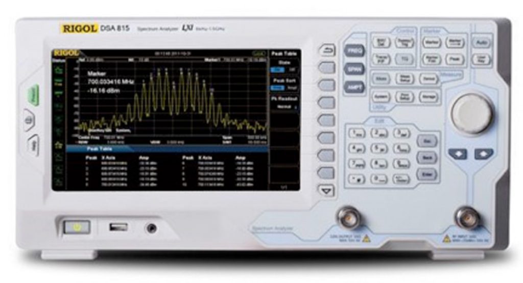
Figure 4 – The Rigol DSA815 is an affordable spectrum analyzer that covers 9 kHz to 1.5 GHz. The base cost is just $1,295. Rigol also has models in the series that cover up to 7.5 GHz. (Photo, courtesy Rigol Electronics).
Another recent offering from Siglent Technologies (http://www.siglent.com), also based in China, is their SSA3000X-series of low-cost spectrum analyzers. It uses the same compact form factor as the Rigol, but is a little wider to accommodate the wider video display. The base unit tunes from 9 kHz to 2.1 GHz, with another model going to 3.2 GHz. There is a similar EMI and tracking generator option. The control layout is similar to the Rigol and easy to use. Both models offer slightly improved specifications in amplitude accuracy and frequency resolution. The free Windows PC software will also help define limit lines and perform automated pre-compliance testing and documentation.
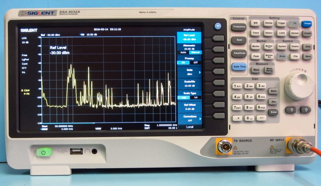
Figure 5 – The new Siglent SSA3000X-series spectrum analyzer tunes from 9 kHz to 2.1 GHz or 3.2 GHz, depending on the model.
Finally, there’s a third option to consider that’s very affordable, considering it has similar specifications as lab quality analyzers. Rohde & Schwarz (https://www.rohde-schwarz.com/us/home_48230.html) recently announced their FPH “Spectrum Rider” portable analyzer, whose base price starts at $5,280 (Figure 6). I also recommend you purchase the built-in preamplifier option for $440. I had a chance to review this and was pleasantly surprised. The unit has much of the functionality as much pricier analyzers, but is a compact battery-operated portable. It will exceed my price total budget for the total troubleshooting kit, though!
The instrument controls are all laid out clearly and I really didn’t need the user guide to start using it. The unit tunes from 5 kHz to 2 GHz, with 3 or 4 GHz as options. While there’s no tracking generator option, the unit does have a lot to offer as far as accuracy and useful features. The battery life is rated at eight hours and the unit is moisture proof with an easy to read display, even in full sunlight. Perfect for field use!
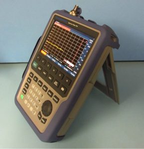
Figure 6 – The Rohde & Schwarz FPH “Spectrum Rider” portable spectrum analyzer tunes from 5 kHz to 2 GHz or an optional upper limit of 3 or 4 GHz as budgets allow. The specifications are very similar to much higher-priced lab quality analyzers and the base price is just $5,280.
Any of these analyzers should do well for you, but my preference (if traveling light) remains the TTi PSA2702T because it’s fast to use and fits so well into the transit case, avoiding my carrying a second piece of gear. The advantage of the Rigol or Siglent analyzers is that they are more accurate than the TTi PSA2702T and include a preamp, tracking generator, the EMI bandwidths and quasi-peak detector. However, for the base price, they’re limited to just 1.5 or 2.2 GHz respectively. The tracking generators are a valuable troubleshooting tool for determining resonances and filter responses. Of course, both Rigol and Siglent have models that go higher in frequency (7.5 and 3.2 GHz, respectively) for additional cost. The Rohde & Schwarz analyzer has even better specifications and is battery-powered, but has no means to add a tracking generator.
Real Time Spectrum Analyzers
If your products include wireless or fast serial data streams, you might wish to consider one of these affordable real-time spectrum analyzers. A real-time spectrum analyzer has the ability to capture brief intermittent signals and are perfect for capturing modulated wireless or digital signals, as well as general EMI troubleshooting. Low-cost examples might include the Tektronix (http://www.tek.com) RSA306 (Figure 7) or Signal Hound (http://signalhound.com) BB60C (Figure 8). Both include feature-rich PC software. Either model should fit nicely into the transit case, as both are relatively small.
For a more detailed review of these two analyzers, as well as several other lab-quality models, be sure to download the new 2016 Real-Time Spectrum Analyzer Mini Guide[2] from Interference Technology.
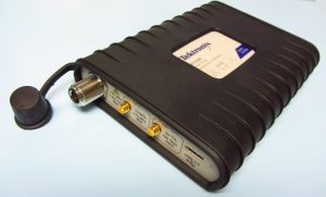
Figure 7 – The Tektronix RSA306 USB-controlled real-time spectrum analyzer covers 9 kHz to 6.2 GHz and has a real-time bandwidth of 40 MHz. The base cost is $3,489 and there are several digital modulation display options.
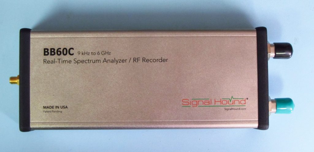
Figure 8 – The Signal Hound BB60C USB-controlled real-time spectrum analyzer covers 9 kHz to 6 GHz and has a real-time bandwidth of 27 MHz. The cost is $2,879.
Real-time analyzers can detect and capture very short intermittent pulsed signals. For example, within the 2.4 GHz ISM band, you’ll see the entire spread spectrum Wi-Fi signal, as well as the frequency-hopped Bluetooth signals very clearly. You can even observe multiple Wi-Fi access points on the same channel. This isn’t possible with normal swept-frequency spectrum analyzers. They also commonly include “waterfall” displays of frequency and amplitude versus time – a very powerful troubleshooting tool for intermittent EMI issues.
Troubleshooting with Spectrum Analyzers
Typically, we’ll use E-field and H-field probes, clamp-on current probes, or voltage probes with spectrum analyzers. These are described more fully later.
For troubleshooting purposes, it’s also possible to use standard oscilloscope probes with spectrum analyzers. Just make sure any scope probe or E-field probe is capacitively coupled in the signal line (or use a capacitive isolation adapter or DC block at the analyzer input), so that large DC voltages won’t be introduced at the analyzer’s sensitive input. That’s a good way to damage the front-end circuitry. Don’t put much faith in the absolute measurement, as a 10:1 probe connected to a 50-Ohm spectrum analyzer input won’t likely be very accurate. However, you can still measure relative improvements as the troubleshooting process progresses. Rigol Electronics has an application note on how to use an oscilloscope probe with a spectrum analyzer[3]
Near-Field Probes
Near-field probes, or “sniffer” probes, are small electric or magnetic field pickup devices used to determine the source of emissions generated by a circuit or component (Figure 9). The E-field probe is essentially a stub antenna at the end of a coaxial line. An E-field probe can be made by cutting away about 1/4-inch of the outer shield, exposing the center conductor. Insulate the end, so it won’t short to anything. The H-field probe is generally a small loop of coaxial cable made by connecting the center conductor to the outer shield. The size of the stub or loop determines the sensitivity of the probe but can also limit its upper frequency range and its ability to localize the source. These near-field probes are easy to make yourself from regular or semi-rigid coax cables.
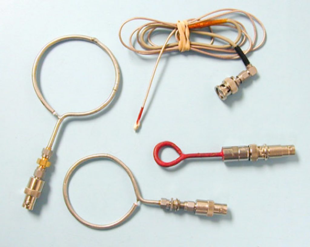
Figure 9 – A few E-field and H-field probes made from short pieces of semi-rigid or flexible coax cables.
Near-field probes can be either very useful or very misleading. Larger probes, which are more sensitive, can pick up ambient readings from high-powered broadcast radio and TV. One way to determine an individual probe’s sensitivity to ambient signals is to measure the frequency range of 88 to 108 MHz in the FM broadcast radio band. If your favorite station shows up on the oscilloscope or spectrum analyzer, you need to be careful to ignore ambient signals. To do this, move the probe away from the unit and power down the unit if possible. If the signal does not go away, you should ignore that particular frequency as an ambient.
H-field probes couple best when oriented in the same plane as the wire, cable, or circuit trace because this allows the most H-field lines of flux to penetrate through the loop (Figure 10). The larger loop probes will be the most sensitive, but not as high a spatial resolution as the smaller loop probes. The smallest probes can trace RF noise currents to a single trace or integrated circuit pin.
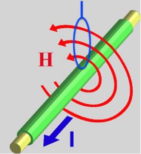
Figure 10 – Proper positioning of an H-field probe for maximum coupling.
Most H-field loop probes are shielded for E-fields, but the capacitance between the shielding and circuit being measured adds a parasitic capacitance that can cause a high-frequency resonance (about 700 to 1,000 MHz, depending on the probe design). By constructing an unshielded loop you can avoid this resonance, but then you also sacrifice rejection of E-fields.
Because most circuit traces are low impedance, and are therefore relatively high current structures, H-fields tend to dominate in digital products. We tend to use H-field probes to locate “hot” signal sources on cables or circuit traces (Figure 11). By carefully sweeping the probe around on the circuit board and interior cables, areas of high emissions can be located. On the other hand, E-field probes are most useful for detecting leakage in chassis seams or gaps, where there might be high levels of E-fields.
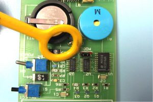
Figure 11 – Using an H-field probe to locate hot spots on a circuit board. For higher resolution measurements, smaller probes should be used.
You need to be careful when mapping out “hot spots” of RF energy. Just because you measure a high field level in a certain part of the circuit board or cable, does not necessarily mean that energy will be coupled out and radiate. It all depends on whether there is a coupling path from the RF energy source to some “antenna-like” structure, such as an I/O or power cable. Generally, near field probes are good for identifying potential emission sources, but I rely on nearby antennas to troubleshoot actual emissions from a product.
If you prefer low cost commercial probes, I can recommend the set from Beehive Electronics (http://beehive-electronics.com) or Tekbox Digital Solutions (http://www.tekbox.net). The Beehive probe set is $300 and you’ll also want to include the 1m long SMB to SMA cable for $50 (Figure 12). Tekbox sells a set of four probes with cable for $200 and the probe set with broadband preamplifier for $330. Saelig Electronics (http://www.saelig.com) is the North American distributor for Tekbox. The Beehive probes may be ordered directly from Beehive Electronics.
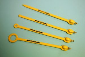
Figure 12 – A typical near-field probe set. In this picture, there are three H-field loop probes and one E-field probe. (Courtesy, Beehive Electronics.)
Current Probes
Clamping a current probe around a wire or cable will measure the common-mode RF currents flowing in that wire or cable. They typically use a toroidal core of broadband ferrite or similar material. The frequency range and sensitivity of the probe will depend on the type of material used and the number of turns of wire wound around the core as a pickup. On emission-only probes, a resistive network is often used to control the impedance and flatten the response. This response is known as the correction, transfer impedance, or transducer factor. Similar current probes can be used to inject RF energy into a cable and are called bulk current injection (BCI) probes. They are used for conducted RF immunity tests.
Current probes are very useful as a troubleshooting tool. Measuring current on certain cables can indicate which cables may be the main cause of radiated emissions. The reduction of RF currents on those cables can often reduce the radiated emissions from the equipment under test. Importantly, by knowing the harmonic common-mode current flowing in the cable at a certain frequency you can calculate the expected E-field emission level and compare to the radiated emission limit. In other words, you can predict pass/fail for a particular cable by simply measuring the RF current through that cable. Refer to the article below for details.
It’s possible to make your own current probes from ferrite toroids or clamp-on chokes (Figure 13). I published an earlier article, The HF Current Probe: Theory and Application, on making and using current probes for Interference Technology in the 2012 EMC Directory and Design Guide[4] and would refer you to that resource for more detail.
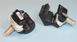
Figure 13 – An example of simple current probes you can make to measure harmonic RF currents in cables.
The advantage of commercial current probes is that they easily clamp around the wire or cable to be evaluated and they are calibrated to accurately read RF current. While the Fischer model F-33-1 probes (http://fischercc.com) are used as an example (see Figure 14), there are many other good manufacturers of current probes, such as Pearson, Rohde & Schwarz, Teseq, Solar, and ETS-Lindgren.
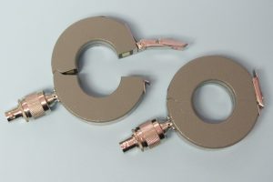
Figure 14 – A matched set of clamp-on Fischer Custom Communications model F-33-1 current probes. While not imperative to purchase, a matched set is very useful for advanced troubleshooting I/O cable emissions. They can sense RF currents of a few microamps.
Antennas
EMI antennas can be very expensive, so I recommend smaller, low-cost antennas, such as the rabbit ears TV antenna still available in some TV and electronic parts stores (Figure 15). UHF TV “bowtie” antennas also work well from 300 to 800 MHz. They will perform just fine for troubleshooting purposes.
Remember, EMC troubleshooting relies more on relative changes, rather than absolute changes. For example, if you know you’re product is failing by 4 dB, reducing the problem harmonic by 10 dB at your own facility, as measured with a nearby antenna, should provide a reasonable assurance of passing.
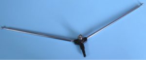
Figure 15 – Simple rabbit ears TV antennas may be used to pick up radiated emissions from a product under test. It will tune from 85 to about 220 MHz depending on how long the elements are extended. Epoxy a BNC connector to the housing and connect each terminal to the telescoping elements.
Also available are low-cost (under $30) PC board broadband log-periodic antennas from Kent Electronics (www.wa5vjb.com) in Figure 16. These are designed for several frequency bands, starting at 400 MHz and have about a 6 dB gain across the band. They work well for general troubleshooting and are what I currently use. Being flat, they fit easily into the transit case.
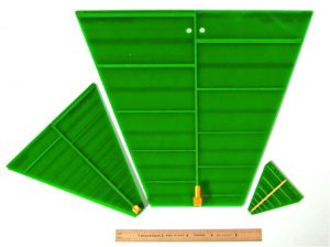
Figure 16 – These PC board log-periodic antennas are low in cost and are resonant in several bands from 400 MHz to 11 GHz. They are available from http://www.wa5vjb.com.
I mount mine using a small tabletop photo tripod and a DIY fixture made from PVC pipe (Figure 17). I tapped and threaded the 90-degree coupling to fit the tripod and used a handsaw to cut a narrow slit in the other end. The PC board just presses into the slot. I left the horizontal piece unglued, so I can rotate the antenna for horizontal or vertical polarization.
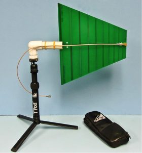
Figure 17 – One of the PC board log-periodic antennas mounted to a tabletop camera tripod. By setting this up near the product under test, the emissions may be observed during troubleshooting.
For a little more cost, I also like the small active broadband antenna from Aaronia AG (Figure 18). Their model BicoLOG 30100X covers 30 to 1000 MHz and includes a battery-operated broadband preamplifier. The cost is just $1,299 and may be ordered directly from Aaronia AG in Germany (http://www.aaronia.com/products/antennas/BicoLOG-30100-X/) or their North American distributors, Kaltman Creations (http://kaltmancreationsllc.com) or Saelig Electronics (http://www.saelig.com). Aaronia also has compact antennas that tune from 700 MHz to 6 GHz.
![]()
Figure 18 – A small broadband active antenna from Aaronia that is very useful for bench top troubleshooting of radiated emissions.
Whether an antenna is resonant at the frequency harmonic of concern is not that important. So long as you can observe the RF harmonics at a distance of 1m, or more, the troubleshooting process can start. Figure 19 shows my typical setup for evaluating and troubleshooting radiated emissions. By monitoring the spectrum analyzer as you try various fixes, you can see immediately whether progress has been made. The best part is that you can do this testing right at your lab bench.
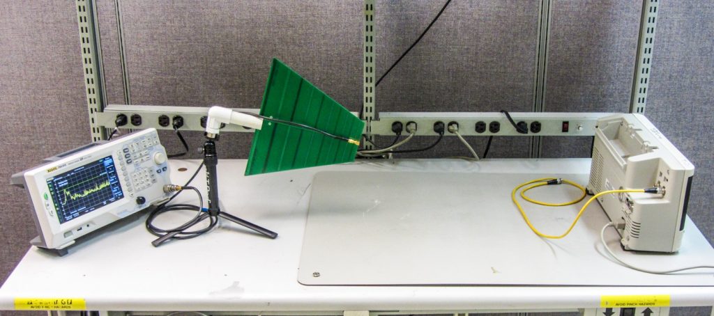
Figure 19 – The typical setup used to troubleshoot radiated emissions. Position the antenna and spectrum analyzer about 1m away from the product under test so you can observe progress in real time.
Ferrite Cores and Chokes
RF currents on cables (and associated radiated emissions) may usually – but not always – be reduced by clamping a ferrite choke around the I/O or power cable nearest the source of RF noise. Adding a few of these chokes in various sizes to your kit would be helpful for troubleshooting (Figure 20). It’s sometimes best to use a large (2.4 inch) toroid ferrite core of 31, or similar, material with multiple turns through it for use in frequencies below 30 MHz. This is a common cure for interference to (or from) consumer equipment. Most common beads and clamp-on ferrites are generally more effective at frequencies in the 100s of MHz, unless the ferrite material is specifically designed for lower frequencies.
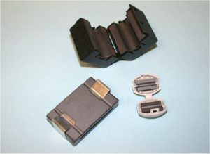
Figure 20 – Examples of various clamp-on ferrite chokes.
Miscellaneous
Adhesive copper tape is also useful for sealing enclosure joints temporarily during troubleshooting. Rolls of this tape may be purchased from electronics distributors at $30, or more, per roll. I’ve also found that “snail tape” (under $10) used in gardening may be substituted. This may be found in garden stores or on Amazon. Take care not to cut yourself on the sharp edges.
Aluminum foil is also handy as a troubleshooting tool for wrapping around an interfering product to assess whether additional shielding might help. Note that aluminum foil is not as effective at power line frequencies.
Finally, a selection of capacitors, resistors, inductors, and common-mode chokes is useful for applying filtering to I/O, microphone, and power line cables.
For more information, feel free to check my web site at http://www.emc-seminars.com, my EMC blog at http://www.design-4-emc.com, or Interference Technology at https://interferencetechnology.com.
Kenneth Wyatt is an EMC consultant and senior technical editor for Interference Technology. He may be reached at ken@emc-seminars.com for consultation or kwyatt@interferencetechnology.com for editorial questions.
[1] EMI Troubleshooting Cookbook for Product Designers is available from Amazon and Stylus Publishing in the U.S., and from The IET in Europe. Go to http://www.emc-seminars.com or http://www.andreconsulting.com for specific links.
[2] Download the 2016 Real-Time Spectrum Analyzer Mini Guide, from Interference Technology here: http://itemmedia.wufoo.com/forms/p17royzx0hl32fe/.
[3] How To Use A Probe with a Spectrum Analyzer: http://www.rigolna.com/products/spectrum-analyzers/dsa800/dsa815/
[4] The HF Current Probe: Theory and Application: https://interferencetechnology.com/the-hf-current-probe-theory-and-application/.
