Optimum antenna selection plays a vital part in effective automotive emissions testing
VICENTE RODRIGUEZ, PH.D.
INTRODUCTION
The following article describes the best antennas for meeting the requirements of full vehicle automotive EMC. The document is divided in to two main sections: Emissions and Immunity. The purpose of this article is to enlighten users on the best solution to their testing requirements.
EMISSIONS
Automotive full vehicle emissions are mainly addressed by the following international standards:
- CISPR 12 “Vehicles, boats, and internal combustion engine driven devices-radio disturbance characteristics – limits and methods of measurement.”
- SAE J551-2 “Test limits and methods of measurement of radio disturbance characteristics of vehicles, Motorboats, and spark-ignited Engine Driven Devices.”
- 95/54 EC Annex IV “Method of measurement of radiated broadband emissions from vehicles.”
- 95/54 EC Annex V “Method of measurement of radiated narrowband emissions from vehicles.”
The International Standards Organization (ISO) does not have any equivalent standard for emissions for a fully loaded vehicle. The ISO standards concentrate purely on immunity as discussed below.
The standards above listed call for testing on an OATS (open area test site) type environment. The OATS must be an area clean of any reflective structures for a 30-m radius measured from a mid-point between the vehicle and the antenna (Figure 1). These are basically the requirements listed in CISPR 16 for any large automotive objects. Both CISPR12 and SAE J551-2 use this wording for the OATS requirements. Annexes IV and V of 95/54 EC use a similar description for the OATS and refers to CISPR 16.
All the above-mentioned standards allow for enclosed test facilities or absorber lined chambers. Their requirement for these facilities is that correlation can be shown between the enclosed site and the OATS.
The best method to show that such correlation exists is to perform an NSA measurement of the enclosed facility per the ANSI C63.4-2000 Standard. If the NSA shows a deviation of ±4dB versus the theoretical curve, then it is safe to say that the chamber performs like an OATS and that measurements taken there can be correlated to those taken in an OATS.
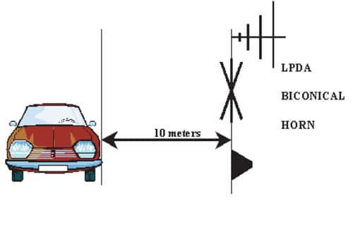
Regarding test method, all standards describe the same test geometry. The antennas will be at fixed height (no scanning as is the case in CISPR16 and ANSI C63.4). The test distance is 10 m, but 3-m testing is accepted. The distance is measured from the antenna to the outer surface of the vehicle under test.
The antenna is to be aligned with the center point of the engine (Figure 2). Also, the vehicle does not need to be rotated, but both sides of the vehicle must be tested (Figure 3).

The antenna is fixed at 3–m above the ground onto which the vehicle rests for the 10-m test distance and 1.8 m for the 3-m test distance. At each point of measurement, readings must be taken for both horizontal and vertical polarizations. The antenna cannot be closer that 1 m to any of the RF absorbent material that lines the chamber walls and ceiling. For vehicles with an internal combustion engine, the vehicle shall be operated during each measurements. Because of this requirement, an exhaust system is required in the chamber as well as a dynamometer. The frequency range is from 30 to 1000 MHz for all SAE J511-2, CISPR-12, and 95/54 EC.
RECOMMENDED ANTENNAS FOR EMISSIONS TESTING
The recommended antennas for emission testing are listed on Table 1. The rest of the present section is dedicated to a description of the antennas in closer detail.

Active Monopole Rod
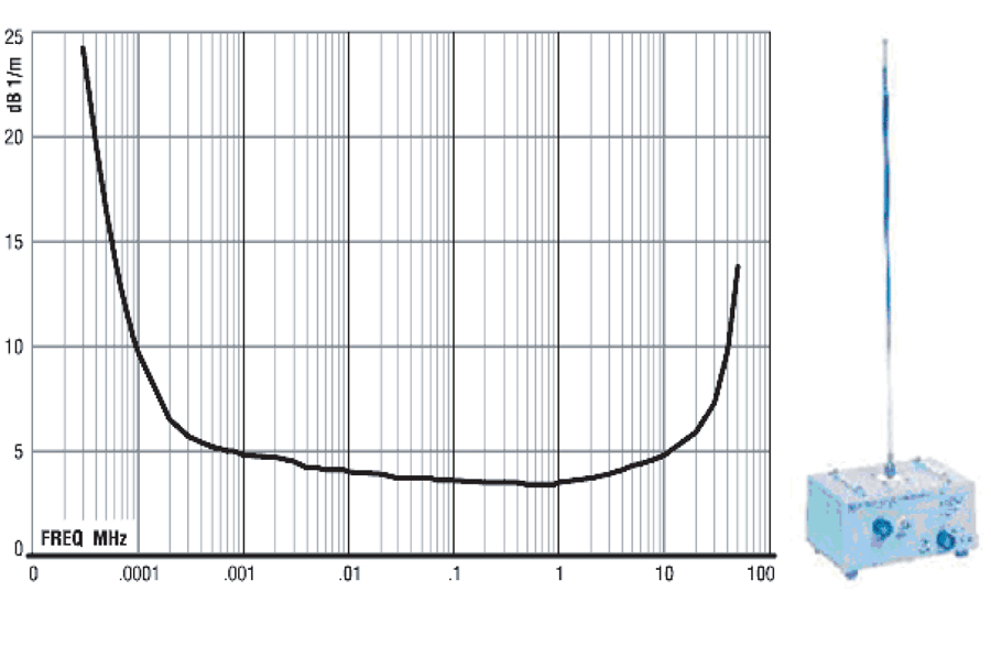
This antenna has an operational range of 30 Hz to 50 MHz (Figure 4). The element is extendable from 50 to 100 cm. It is provided with a 60-cm x 60-cm ground plane to meet the requirement of several standards. These are, in general, very ineffective antennas because of their small electrical size. They are usually provided with a preamplifier unit forming part of the antenna.
Biconical Antennas
These antennas have been used in EMC for testing at low frequencies and are the recommended antennas in a lot of standards from MIL-STD 461E2 to some of the automotive component standards such as CISPR 25 (Figure 5). The typical biconical antenna usually has a range of 20 to 300 MHz; however, it is recommended that they be used from 30 MHz to 200 Mhz, the range in which they offer their best performance as compared with other
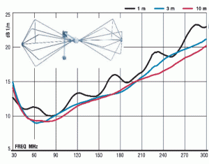
antennas.
Log-periodic Antennas
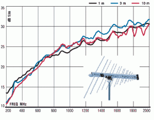
From 200 MHz to 1 GHz, it is recommended that a log-periodic antenna be used (Figure 6). Log-periodic antennas have a typical range of 200 MHz to 2000 MHz or 3000 MHz depending on the manufacturer. Larger log-periodic antennas with operating ranges down to 80 MHz are also available. Usually, the antenna factor (AF) of the log-periodic antenna is better than that of the biconical. Therefore, it is always possible to use the biconical up to 100 MHz and then to switch to a log-periodic with a 80-MHz to 1000-MHz range. The 80-MHz to 2000-MHz log-periodic models are very large and not as easy to handle as the 200-MHz to 2000-MHz types. If a lot of testing with frequent antenna changes is anticipated, it is better to use the biconical and a 200-MHz-2000-MHz log-periodic.
Dual Ridge Horns
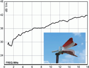
Dual ridge horns have been used in EMC for over 30 years. Recently their use came into question3 because of irregular pattern behavior at higher frequencies. There are, however, newer models on the market that correct the pattern problems of the traditional dual ridge horns.4,5The new dual ridge horns are antennas with improved pattern behavior above 10 GHz. These improvements translate in a more constant antenna factor and gain (Figure 7).
Optional Hybrid Antennas
If a high rate of testing is expected, and if the user needs to minimize the switching of antennas, a biconical-bowtie/log-periodic hybrid can be used. These antennas typically have a frequency range extending from 26 MHz to 3 GHz; they can be substituted for the biconical and the log periodic antennas. There are, however, some standards that prefer the use of log periodic and biconical antennas instead of hybrid combinations. Additionally, it is important to select a hybrid antenna with a good bowtie to log-periodic transition that shows no bumps or spikes in the AF in the 70-MHz to 200-MHz range (Figure 8).
The combination of the antennas presented above will cover all the needs for emissions testing from full vehicles per the product test standards.

IMMUNITY
Immunity applications in automotive EMC standards call for the generation of very high fields. This section proposes a solution to meet the immunity requirements of full vehicle testing for the 100-kHz to 18-GHz range.The main standards that the recommended solution addresses are the following:
- ISO 11451-2
- SAE J551-11
- 95/54 EC Annex VI
All these standards have similar wording. The SAE and the ISO are virtual copies of each other, and they both require a high severity level of 100 V/m.1 ISO contemplates an additional level of severity to be agreed upon between the test house and the manufacturer. This document assumes that the additional level of severity is an internal requirement of the customer that does not fall within the standard. The present solution concentrates on field levels lower than or equal to 100 V/m.
Additionally, the solution presented assumes that the field uniformity requirements are those stated in the standard. These requirements specify (for SAE and ISO) that the required field level be generated at a reference point located 1 m above the ground on which the vehicle rests (2 m for vehicles higher than 3 m) and at two points 75 cm on either side of the reference point. At these points, the field level should be within 3 dB of the reference level. For 95/54 EC the points are 50 cm on either side, and the highest level of severity is 24 V/m with 80% AM modulation. For 95/54 EC the field at the adjacent points must be at least half of the field at the reference point.
For SAE and ISO, the Field Uniformity requirement applies over 200 MHz; for 95/54 EC it applies above 20 MHz. Both polarizations can be tested if required by the standard document.
Solution
The antennas for field generation that are recommended in this article cover the 100-kHz to 18-GHz range. As might be expected, several antennas and a transmission line system are required for this range. An E/H field generator is used for the 100-kHz to 30-MHz range. A high power biconical antenna is the recommended choice for the 30-MHz to 100-MHz range, and a double ridge guide horn for the 100-MHz to 1-GHz range. These antennas are the best possible solution to meet the requirements of the SAE and the ISO standards. Above 1GHz, the suggested solution is the use of octave gain horns or standard gain horns.
The 95/54 EC standard document describes the testing of immunity over the 20-MHz to 1-GHz range with a severity level of at 24 V/m with 80% AM modulation. The use of a foreshortened log-periodic and dual log arrays is better. However, foreshortened logs place the low frequency elements too far from the reference point to be able to generate the very high fields required by the SAE and the ISO standards. For the 95/54 EC directive, where the field levels are low and the range of frequencies not too wide, the foreshortened log-periodic and dual log arrays can meet the requirements with power levels of 5 kW maximum.
100 kHz to 30 MHz Testing
For frequencies below 30 MHz, manageable size antennas are not very efficient. Wavelengths rise to the order of tens of meters and half wavelength resonant radiators become too large to fit inside a chamber. Consequently, all the above-mentioned standards allow for the use of transmission line systems or TLS.
There are different types of TLS that can be used. In some of them, the element is a solid plate that is driven against ground to generate a vertical electric field between the plate and the floor similar to one present in a capacitor. It is important to have a good terminal resistor for the TLS so that no standing waves appear along its length. Another type of TLS system consists of two conductors suspended above ground (Figure 9).
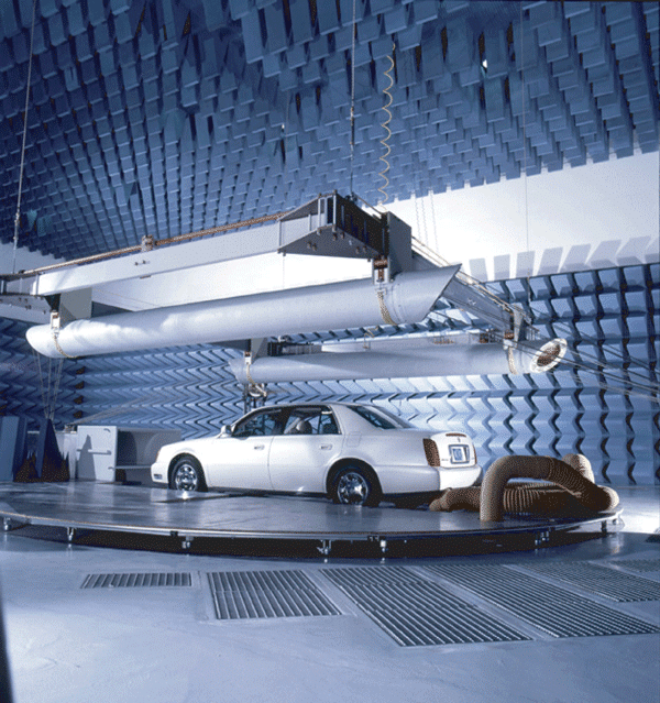
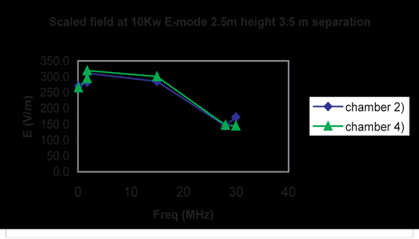
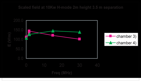
As can be seen in Figure 9, the structure is supported from the ceiling by four anchor points. The elements can be both driven together against the ground (even mode) or against each other isolated from ground (odd mode). The even mode (Figures 10) generates a vertical polarized electric field while the odd mode (Figure 11) generates a horizontal polarized electric field.
High Power Biconical
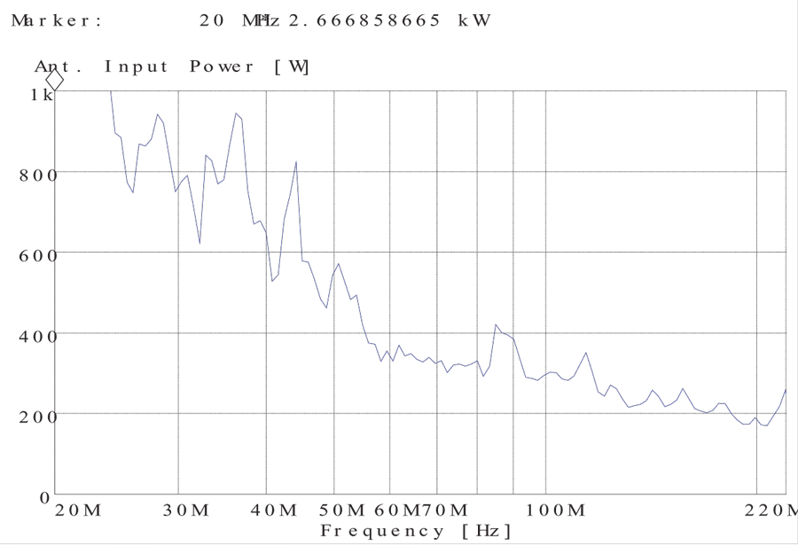
A biconical type antenna with a high power balun and construction is the recommended solution for the 30-MHz to 100-MHz range (Figure 12). At these frequencies, the antennas are not very efficient since they must be very long to be half wavelength type resonators. The biconical design is the most economical and efficient for this frequency range. Even so, a 10-kW amplifier may be needed to generate some of the severity levels required by the ISO and SAE standards. The biconicals have the advantage over large log-periodic antennas in that the radiating elements are the same at all frequencies. Hence, the radiating element at the lowest frequency (where the antenna is the least efficient) can be placed close to the vehicle and reference point without violating the 50-cm distance between the antenna and the vehicle. With a log-periodic antenna at the lowest frequency, the back elements are radiating. These can be as much as 2 meters from the tip of the antenna, placing the radiating elements as far as 4 meters from the reference point in some cases.
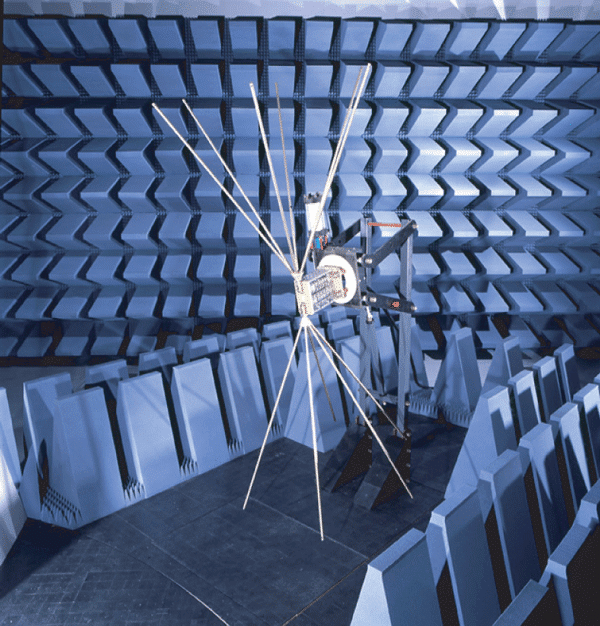
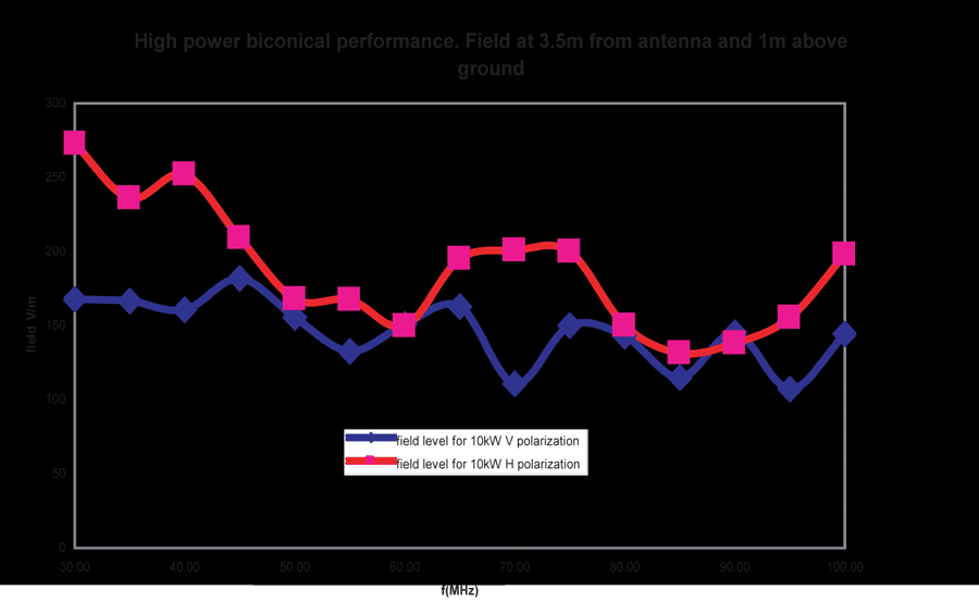
The graph in Figure 13 shows measurements that were performed with the antenna placed 2 m above ground and 3.5 meters from the reference point. The reference point was located 1 m above the ground.
Dual-ridge Horn Antennas
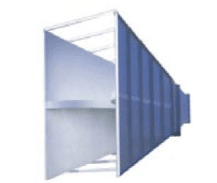
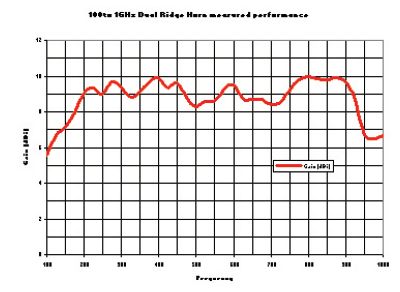
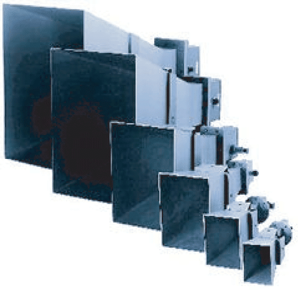
Larger dual-ridge horns are now available (Figure 14). These new horns bring down to 100 MHz the behavior of the typical traditional dual-ridge horn used from 200 MHz to 1 Ghz in MIL-STD 461E.2 These horns have gains of 9 dBi on average which is more than the typical log-periodic antenna used in EMC.
The gain of these horns at the lowest end of its operational range is about 5 dBi (Figure 15). The gain improves to a level higher than 8 dBi at about 150 MHz. The gain stays higher than 9 dBi up to 950 MHz, where it drops down to 7 dBi at 1 GHz.
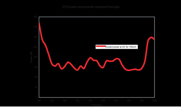
Using these gain values, it is possible to derive the required power to attain 100 V/m at 2 meters distance (2 m is the minimum distance between the reference point and the antenna phase center according to all the standards). The computation shows that 500 Watts is all that it is needed to obtain the required 100-V/m CW field levels at a distance of 2 m from the aperture (Figure 16). (NOTE: computed data do not take into account the cable loss, but give a general idea of the power requirements.).
Some vendors offer dual log-periodic arrays to increase the gain of their log-periodics. These are structures just as large as the 100-MHz dual ridge horn, and they require the use of power splitters and phase match cables, which increases the cost.
Above 1-Ghz Testing
Above 1 GHz, amplifiers are more expensive, therefore, higher gain antennas are the best possible approach. For that reason, the use of octave gain horn antennas is recommended. These antennas have gains of about 15 dBi minimum.
Optional Solution 95/54 EC (20 MHz to 1000 MHz)
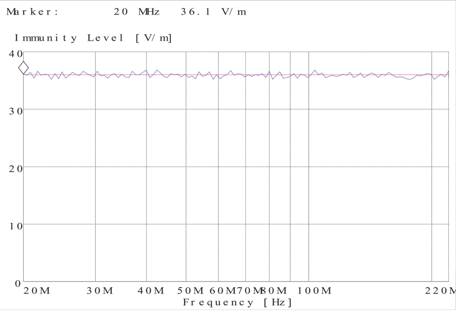
The 95/54 EC annex VI standard is a much more relaxed specification than the SAE or ISO immunity documents. The severity level for the immunity test is 24 V/m at 80% modulation from 20 to 1000 MHz. The recommended solution for this particular standard consists of a foreshortened logarithmic periodic antenna for the 20-MHz to 200-MHz range and a dual array of logarithmic periodic antennas for the 200 to 1000-Mhz range (Figure 17). The two antennas can be mounted on a single positioner that allows for remote polarization and tilt of the antennas from 10 to -45 degrees.
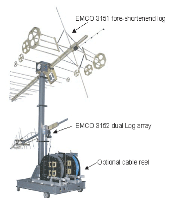
This solution is better suited for chambers that are larger than 9 m of height. In smaller chambers, the resonant behaviors are excited in the range of 20 to 30 MHz. Based on the data above, 36 V/m can be generated at 3 m from the tip of the antenna with less than 3 kW of power.
Overview Of The Recommended Antennas
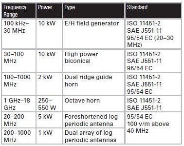
Table 2 presents an overview of the recommended antennas and the optional solutions presented in this document. Two device controllers are needed for the 95/54 EC solution. For the dual ridge horn and the biconical type antenna with a high power balun, two device controllers are also necessary to control both positioners.
CONCLUSION
This article has shown recommended antenna solutions for automotive EMC testing to meet the requirements of the most important international standards.
REFERENCES
- Society of Automotive Engineers (SAE) Surface Vehicle Electromagnetic Compatibility (EMC) Standards Manual. Society of Automotive Engineers, Inc. Warrendale, PA. 1999.
- MIL-STD 461E, “Requirements for the Control of Electromagnetic Interference Characteristics of Subsystems and Equipment.” Department of Defense. August 1999.
- C. Burns, P. Leuchtmann, R. Vahldieck. “Analysis and Simulation of a 1-18-GHz Broadband Double-Ridge Horn Antenna.” IEEE Transactions on Electromagnetic Compatibility, Vol 45, No 1. Feb 2003. pp 55-60.
- V. Rodriguez-Pereyra. “New Broadband EMC Double-ridge Guide Horn Antenna.” RF Design. May 2004. pp. 44–50.
- V. Rodriguez. “A New Broadband Double Ridge Guide Horn with Improved Radiation Pattern for Electromagnetic Compatability Testing.” 16th International Zurich Symposium on Electromagnetic Compatibility. Zurich, Switzerland. February 2005.
VICENTE RODRIGUEZ-PEREYRA attended the University of Mississippi where he obtained his B.S.E.E. in 1994. During the fall of 1994, he joined the Department of Electrical Engineering at the University of Mississippi as a research assistant. He was involved in projects regarding reduction of crosstalk in high speed digital circuits as part of an Army Research Office grant and on the use of the Finite Difference Time Domain technique in antenna analysis. During this period, he completed his Master of Science and Doctorate in the area of Engineering Science with an emphasis on Electromagnetic Theory in 1996 and 1999, respectively. In August 1999, Dr. Rodriguez joined the Department of Electrical Engineering and Computer Science at Texas A&M University-Kingsville (formerly Texas A&I University) as a Visiting Assistant Professor. In June 2000, Dr. Rodriguez left the academic world when he joined EMC Test Systems (now ETS-Lindgren) as an RF and Electromagnetics engineer.In September 2004, Dr. Rodriguez took over the position of Senior Principal Antenna Design Engineer, placing him in charge of the development of new antennas for different applications and improving the existing antenna line.
Dr. Rodriguez’s interests are Numerical Methods in Electromagnetics, especially when applied to antenna design and analysis. Since his association with ETS-Lindgren, Dr. Rodriguez’s interest has expanded to the use of these numerical techniques in designing EMC and RF/MW absorbers. Dr. Rodriguez is the author of more than 20 publications including journal and conference papers, as well as book chapters. Dr. Rodriguez holds a patent for hybrid absorber design. Additionally, he has a patent pending for a new dual ridge antenna horn antenna design for EMC applications.Dr. Rodriguez is a member of the IEEE and several of its technical societies including the MTT and the EMC Societies. Dr. Rodriguez is also an active member of the Applied Computational Electromagnetics Society (ACES). He is an Associate Editor of the ACES Journal and chair of the member communications committee of ACES. Dr. Rodriguez has served as a reviewer for the ACES Journal and for the Journal of Electromagnetic Waves and Applications. He has co-chaired a session during the 2003 ACES Symposium, and workshops during the 2002 and 2004 IEEE International Symposia on EMC. Dr. Rodriguez is a full member of the Sigma Xi Scientific Research Society and of the Eta Kappa Nu Honor Society.

