
Introduction
The number of connected devices keeps growing every year. Millions of devices exchange data wirelessly to make our lives easier.
Wireless connectivity simplifies installation by removing cables, but it uses the electromagnetic spectrum, which is becoming more and more crowded.
User demands have shifted connectivity from being a convenience or a cost-reducing feature to a must-have one. Users do not want to replace the functionality of a smartphone with a wired connection.
As a result, manufacturers of all kinds of devices are under pressure to add wireless connectivity to their products from day one. They can do it by using RF modules, which reduce the development and integration time.
However, there is a common misunderstanding: modules reduce the time needed to build a prototype, but they do not reduce time to market to the same extent.
The legal requirements for electromagnetic compatibility and radio are largely the same for a device incorporating a module as for a device with an RF circuit designed from scratch.
To fulfill these legal requirements, we need to measure how RF devices behave. With the number of devices increasing every day, we need to make measurements very accessible.
If we want more designers to understand RF, we need to make both the knowledge and the tools more accessible.
This article looks at the main challenges of designing IoT devices with wireless connectivity and shows practical RF test devices and setups to reduce the time to market.
Challenges in IoT Devices
RF manufacturers have done a great job over the last decade lowering the entry barrier. By packaging complex RF knowledge into modules, they have made wireless connectivity much easier to integrate into new products.
Designers can build a first working prototype very quickly, sometimes just by placing a module on a reasonably designed PCB and following the reference design.
That is a huge advantage, but it also creates a common misunderstanding. Because modules make RF integration look easy, many teams assume that the RF part is already solved.
In reality, a module can simplify development, but it does not eliminate the need to understand how the full device behaves once the module is integrated into a real product.
Furthermore, it does not eliminate the need for radio or Electromagnetic Compatibility (EMC) certifications. What is tested is the whole product, not just the RF module.

Teams may be very capable in PCB design, digital electronics, firmware, or mechanical design, but have much less experience with high-frequency effects.
As long as the prototype communicates in laboratory conditions, everything looks fine. Problems often appear when the device is placed in its enclosure, surrounded by noisy electronics, or connected through cables.
It is common for manufacturers to wait until the product is finished to start making RF measurements, accumulating risk and avoidable delays.
Most of the time, designers learn RF the hard way: through trial and error until the product finally passes the tests.
In RF systems, interference problems and weak communication links become functional problems. If communication only works under specific conditions, users will notice.
Detecting these problems late in development is expensive and frustrating. This is why teams should not leave RF evaluation until the end of the project.
Early RF measurements help designers detect these problems while they are still manageable.
The Minimum RF Bench
The word “affordable” means different things to different people.
For some, it means spending less than a few hundred euros. For others, it means staying below the cost of a full professional RF bench while getting meaningful results.
This article gives some examples of devices that can be used, so it is not an exhaustive list. In the reference section, you will find articles with comparisons of different types of equipment.
There are many types of instruments on the market, some of them highly application-specific.
To start increasing the quality of your devices, you just need two: a Spectrum Analyzer (SA) and a Vector Network Analyzer (VNA).
Spectrum Analyzers
In RF work, observing signals in the time domain is not enough. We care about energy distribution across the spectrum.
Spectrum Analyzers (SA) are one of the most useful instruments in RF development.
They allow us to observe signals, harmonics, spurious signals, emissions and noise in ways that oscilloscopes cannot.
Vector Network Analyzers
While spectrum analyzers show how signal energy is distributed across frequency, VNAs show how RF energy behaves at ports such as connectors, traces, and antennas.
For wireless products, this is essential because many problems are not caused by the lack of signal, but by poor power transfer.
A VNA makes it possible to evaluate matching networks, antenna ports, and RF paths in a much more systematic way.
For IoT devices, VNAs are especially useful when tuning antennas and matching circuits, where small changes in layout, enclosure, or nearby elements can affect performance.
Types of Equipment
Once your measurement needs are clear, the next question is where and how those measurements will be made. It is important to have a rough idea because choosing the right equipment will make your life easier.
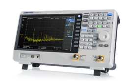
Bench-top Equipment
Bench-top Spectrum Analyzers are easy to use and manufacturers tend to build in the same interface as with the top-tier ones. They are enough to start answering important questions early in the project.
Until recently, bench-top analyzers were reserved for teams with mid to high budgets.
That has changed. Several manufacturers now offer entry-level and mid-range instruments that are much more accessible to universities, consultants and small companies.
The tradeoff is that the affordable range of equipment comes with limitations in phase noise, dynamic range or frequency range.
USB Equipment
USB spectrum analyzers sit between very low-cost portable tools and full bench-top instruments.
Because they rely on an external computer for display and storage, they can offer useful RF capability at a lower price and in a more portable format.
This makes them attractive for designers who need measurements outside the lab or who want a lighter setup than a traditional bench-top analyzer.
The downside is that their usability depends strongly on the computer and the software.
For occasional measurements or portable troubleshooting, they can be a good compromise between cost, capability, and portability.

Handheld Devices
To make portable measurements even easier, handheld Spectrum Analyzers are more convenient than USB ones.
Handheld ones are the best option for people that are constantly on the move, making field measurements, or debugging directly on installed equipment.
They have an integrated screen and a battery, removing the dependence of external elements.

Low-Cost Tools That Reduced the Entry Barrier
TinySA
TinySA made RF measurements with a device that costs less than one hundred dollars.
It revolutionized the world of amateur radio by providing not only frequency measurements, but also a signal generator.
Due to its portability and its ability to work as a high-frequency signal generator, it is a purchase that makes a lot of sense.

NanoVNA
NanoVNA has done for VNAs something similar to what TinySA did for spectrum analyzers: it lowered the barrier to entry drastically.
For a very low price, designers measure return loss, impedance, and matching networks instead of working blindly.
It is an extremely useful tool for learning, antenna tuning and debugging.

Enjoying this article?
Subscribe to Interference Technology for expert coverage of EMI, EMC, and signal integrity challenges—plus immediate access to new digital magazine issues.
Subscribe here →
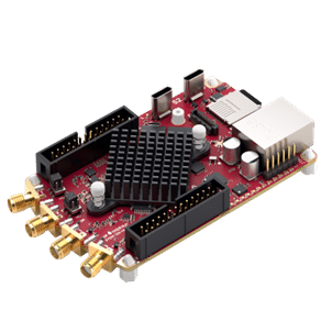
FPGA-Based Multifunction Boards
A lesser-known type of device is FPGA-based multifunction boards such as the RedPitaya.
Since the main device is reconfigurable, a board with one provides a lot of flexibility. Boards like these can be configured to be an Oscilloscope, Spectrum Analyzer and many other measurement options.
They are open-source with a huge community behind them, which makes them suitable for Academia and research applications.
The trade-off is the set-up complexity and the expertise needed to make sure they work properly.
The Minimum RF Bench
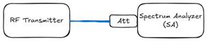
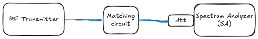
Measuring Output Power
Output power is the first functional verification.
It answers two questions: is the transmitter transmitting and is the transmitter transmitting the desired power?
The set-up is simple, but do not forget to:
- Use an attenuator. It is less painful to correct the measurement than to buy a new spectrum analyzer.
- Account for the losses introduced by the cable and the attenuator.
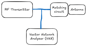
Matching the RF Path
If the transmitter is active, but the RF link is still weak, it is usually poor matching.
Mismatches provoke losses, so designing an efficient RF link requires a careful matching of the elements from the transceiver until the antenna.
With the VNA, you will see what the transmitter “sees”, and the impedance should be constant to maximize the output power.
To save time and energy during the tuning process:
- Provide a RF path to connect the VNA, like a small coaxial connector on the board.
- Ensure the set-up one step at a time: remove surrounding elements, calibrate, check the cables. Repeatability is critical in this process.
Checking Harmonics and Spurious Emissions
Once the transmitter is working and providing the desired output, the next question is: is it generating unwanted signals?
Harmonics and spurious emissions are a common problem in IoT wireless devices, and they can delay or block market entry. It is important to identify them as soon as possible.
We start with conducted measurements, connecting the output through a cable, to identify potential problems at early stages.
Simple Radiated Pre-Check
Once the conducted tests are successful, we should check what happens over the air.
While it is not a test that replaces compliance measurements, a simple radiated pre-test is very useful.
The challenge when doing radiated measurements is the poor repeatability due to the environment, so do not consider these tests as definitive unless you have the proper environment (an anechoic chamber or an Open Area Test Site).

To keep a good repeatability, keep elements fixed (position and orientation) and remove surrounding elements.
At this stage, the goal is a rough far-field-style comparison, so the antenna spacing should be large enough and kept consistent.
Conclusion
Early RF testing is powerful, it helps reduce uncertainty before reaching the market. Of course, it has limitations, it does not replace accredited EMC or radio testing.
Nevertheless, the goal is not to have accurate measurements since the beginning of the project, but to reduce risks step by step and avoid expensive surprises.
By implementing early stage measurements, the development team will be familiar with the processes and they will arrive at the certification laboratory more relaxed.
References
- https://www.siglenteu.com/spectrum-analyzers/
- https://www.tek.com/en/products/spectrum-analyzers/rsa306
- https://interferencetechnology.com/new-low-cost-spectrum-analyzers-announced/
- https://interferencetechnology.com/assembling-low-cost-emi-troubleshooting-kit-part-1-radiated-emissions/
- https://interferencetechnology.com/assembling-low-cost-emi-troubleshooting-kit-part-2-immunity/
- https://interferencetechnology.com/do-you-have-suggestions-for-a-low-costused-spectrum-analyzer-for-pre-compliance-testing/
- https://tinysa.org/
- https://nanorfe.com/nanovna-v2.html
- https://redpitaya.com/