Taking these factors into account can save time and money.
Gary Fenical,
Laird Technologies
Delaware Water Gap, PA
RF shielding materials are an important consideration when designing electronic components because these materials help ensure that the electronic device will perform to its optimum functionality. Considering RF shielding materials at the beginning of the application design phase assures that the right materials are chosen and that issues can be identified and dealt with early on in the process—a strategy that saves money and keeps the project on time. Choosing the correct materials upfront ultimately gets the product to market quicker.
This article will discuss factors to consider when selecting RF shielding materials for an electronic device. Taking these factors into account can save time and money and help assure peace of mind when designing an electronic device.
Cost
Cost is always an important consideration and can be a complex subject. The cost structure of RF shielding materials reflects a number of factors. A generalized breakdown of the costs for producing RF shielding materials is one-third material, one-third labor, and one-third overhead.
This article will provide a sample plan to assist in determining precisely what factors must be considered to reduce the cost of dealing with the mitigation of EMI. The plan will ensure the RF shielding material meets mandatory requirements and will help get the end product to market in a timely and efficient manner.
The chart in Figure 1 shows that EMI costs can be held to a minimum if they are considered at the beginning of the project. Problems and issues become more costly the farther into a project they are discovered. If problems are uncovered too late in the development phase, a product might fail to meet requirements and not make it to market at all.

 At the beginning of the project, setting up an EMC Advisory Board is strongly recommended. This is especially important for large projects. Membership should consist of representatives from all subsystem suppliers. The experts on the Board are charged with providing advice and overseeing product development. The Board should begin by developing an “EMC Management Plan” complete with organizational responsibilities including:
- Lines of authority and control
- An implementation plan
- EMC requirements for sub-systems and suppliers
- An EMI control plan
- Reporting procedures
A comprehensive “EMI Control Plan” should be developed, and it can be organized as detailed below.
- Introduction
- Project details
- Purpose of plan
- Product use and environment
- Applicable documents
- Analysis
- Modeling and predictions
- Special features
- Risk areas
- Control precautions
- Mechanical
- Electrical
- Testing
- Mandatory requirements
- Customer requirements
- Optional requirements
- Planning
- Prototype tests
- Subsystem tests
- System evaluation
- Reporting results
- Test facility requirements
- Mandatory requirements
- Final documentation
- Review for applicability
- Determine location for accessibility by authorities
- Determine how long it must be maintained
EMC Test Plan
After the EMI control plan is created, the next step is the creation of an “EMC Test Plan” consisting of:
- System description and operation
- Power requirements
- Operating modes
- Peripheral equipment necessary
- Test layout
- Cables and wiring
- Special fixtures
- Exercising peripherals
- Performance and failure criteria
- Test methods and specifications
- Special requirements
- Final report format
Final Test
For certification testing, plan the following:
- Prior to the test:
- Plan
- Budget
- Select and book facilities
- During the test
- Attend the tests
- Confirm applicable specifications
- Isolate and investigate failures
- Fix failures on site if possible
- Confirm proper operation
- Attend the tests
- After the test
- Obtain the report
- After all, this is what is really needed to go to market
- Maintain the files for the required period of time for the standard met
- Obtain the report
A carefully executed EMI control plan will show where RF shielding materials will be required. At this time, it is wise to contact a manufacturer that provides comprehensive engineering services to assist in selecting the proper and least expensive solution to meet the RF shielding predictions. Remember, not all RF shielding suppliers have engineering services. RF shielding is a complex subject and requires experience and trained engineers familiar with both the nuances of the materials and geometries required. Simply going to a catalog and trying to pick out an RF gasket or shield for an application rarely works.
Standard Products
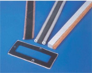
Standard, off-the-shelf shielding products are the most cost effective (see Figure 2). If it is known at the beginning of the project that the design requires shielding materials such as PCB, shields, RF gaskets, ferrites, etc., it is easier and more cost effective to design in standard products. Obviously standard products are in stock and readily available. Also, generally they are of the highest quality and have well defined tolerances. If a product has proved reliable in many applications, the manufacturer will likely keep making it available to customers.

Careful design and planning are vital. If a PCB shield is required, provisions must be provided for soldering it to the board. Otherwise, installation will be impossible. Similarly, there must be a solid ground plane level to provide the “sixth” side of a Faraday cage. The PCB shield is only five-sided. If RF gaskets are required, it is essential to provide the proper sized and shaped surface to achieve effective installation. Also, as opposed to soldering or screwing, less expensive installation methods such as pressure sensitive adhesive (PSA), form-in-place (FIP) elastomer, or clip-on metal and/or fabric-over-foam (FoF) gaskets may be used.
Electrically conductive elastomers (EcE) that are hollow will reduce material costs as well as compression forces. These must be extruded and cannot be molded into complex shapes. However, there are quite a number of such hollow profiles available as standard products, and they are therefore less expensive than custom-molded shapes.
Modified Standard Products
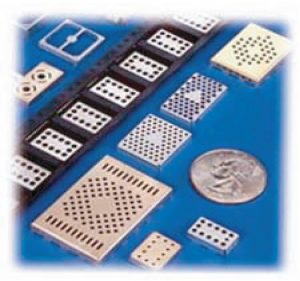
A cost-effective alternative to standard products is modified standard products, such as shown in Figure 3. Many times a standard profile or shape may come close to doing the job but just will not work. In these cases, modified standard products are recommended. Most standard profiles can be modified in various ways to provide a custom RF gasket or PCB shield without incurring the costs of custom tooling.

Many manufacturing processes used for producing standard products can be altered to produce “modified standard” products. Sometimes it is just a matter of changing the base material or the thickness of the material. Usually, it is a matter of cutting to length, removing fingers, adding holes, extending or reducing dimensions, or adding secondary operations such as bends or various geometries. In such cases, it is necessary to work with a knowledgeable engineer who knows what modifications can be made to the standard products to produce an altered product that fits a particular design.
Custom Products
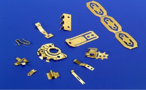
Custom RF shielding products (Figure 4) still play a large role in the design of electronics products. Obviously, custom profiles are the most expensive. Costs are incurred from engineering, prototyping, tooling, and piece price. However, if a custom product is required, it is imperative that an engineering company be chosen, rather than just a manufacturer. A true engineering company will have an engineer properly design the required custom product. A trained RF shielding engineer will take many specific factors into account. The first factor is the base metal. Does the application require the exceptional properties of beryllium copper (BeCu), or will a less expensive material work? In the case of elastomers, what elastomeric/conductive filler combination is the best? For conductive fabric, what fabric/foam combination will fit the bill? For PCB shields, is a one-piece or two-piece design required? On the other hand, is an E-Z peel or drawn shield better? All of the possibilities can be overwhelming.

Custom Product Examples
Most problems can be avoided and costs reduced by following a few simple rules:
- Always fabricate enclosures from the fewest number of pieces and utilize existing metal structures such as the ground layer in the PCB, internal metal divisions, or disk drive base plate as part of the shield. Eliminate free-floating pieces of metal.
- Use RF gaskets as seals for removable discontinuities. The five major types of gasket configurations used in today’s systems and enclosures are beryllium copper spring fingers, beryllium copper hollow tubular wire mesh, Monel/SnCuFe and other metal solid wire mesh, fabric-over-foam conductive fabric over a foam core, and metal-filled conductive elastomers. Each type of gasket lends itself to advantageous use in certain applications. A designer must be knowledgeable about the qualities of a particular gasket and the demands of a specific application. Then the optimal choice can be made.
- Design removable panels, covers, and doors to provide controlled gasket compression. Except for elastomers that continue to improve under compression, tests have shown that other gaskets yield little or no improvement in performance once good contact has been established. Gasketed joints are not rigid and tend to bulge open between fasteners. This distortion can cause a discontinuity and result in an RF leak. Be sure to choose a gasket with both minimum compression force and maximum working height range, and be sure to provide a positive stop.
- Whenever possible, use a knife-edge or pan-edge panel arrangement for doors and access panels. This arrangement eliminates the need for periodic threaded fasteners to preserve the shielding effectiveness of the enclosure.
- Use the largest gasket possible. Small gaskets have a limited working height range. This limitation demands that close gap tolerances be maintained in the shielded enclosure. The cost of maintaining close tolerances will greatly exceed that of opting for larger shielding gaskets. Moreover, smaller gaskets tend to be stiffer than larger ones. Consequently, the enclosure must be more rigid to avoid excessive distortion. Increasing structural rigidity will usually add to the cost of an enclosure.
- For shear applications, a finger gasket is normally used. Always wipe toward the free end of the finger. In most finger gasket installations some wiping action occurs. It may be deliberate, or it may occur incidentally—for example, on the hinge side of a door when the gasket is used in compression. In either case, engaging the gasket from the wrong direction will damage the fingers and will impair shielding effectiveness. Note that when a gasket is compressed wiping in either direction will work.
- Protect the gasket from snagging or tearing. Gasket material should be mounted where it is least likely to be damaged by people or objects. For large doors, it is usually better to mount the gasket on a door frame where some protection is afforded. For removable panels, it is usually better to mount the gasket on the panel so that when the panel is removed, the gasket is no longer near the work area.
- Shield gaskets should be installed to provide the highest surface conductivity, conductive-to-conductive condition. If the mating materials must be environmentally protected, the protective coating should be electrically conductive. If the gasket includes a separate environmental seal, that seal should be facing the external environment.
- In all cases, the gasket material should be selected or plated to achieve galvanic compatibility. Tables are available that provide a list of compatible materials, along with the various platings that are available.
Material
Many times high-performance material such as beryllium copper is not required. Although it is arguably the best metal material for RF gaskets, it is not always required. Other material such as phosphor bronze, stainless steel, or cold-rolled steel may be an acceptable choice. There are also other considerations such as pre-plating with bare edges allowed, or even in lower volumes, allowing one bare edge so that the part can be processed in batches rather than one at a time.
Other Considerations
- Volume
- Placing larger blanket orders with set release dates will allow the RF shielding manufacturer to plan ahead and will lower the price. This allows the manufacturer to acquire larger amounts of material at a better per-volume price. Effective forecasting also allows a manufacturer to dicker with suppliers, thus further reducing material costs. .
- For high volume custom parts, tooling of high-speed progressive dies will reduce piece price. This choice is especially advantageous if volume is expected to increase. Up-front costs are higher than choosing secondary tooling, but a lot of handling down the road is eliminated. High-volume tooling is also a factor in holding down costs when modified standard products are used. For low- to mid- volume parts, having all form lines parallel is a savings. When designing custom shielding, try to incorporate readily available parts (such as a “D” lance) whenever feasible. This decision always saves tooling money and sometimes even lowers the piece price.
- Set up a safety stock program so that larger orders can be run through in one batch, thereby reducing the number of times the machines must be set up and run.
- Specifying material
- Factors such as alloy, gauge, finish, etc., affect price. Specify a material the manufacturer uses frequently, and some of the savings of buying in volume will be reflected in the final price of the shielding design. Rare materials will, of course, drive up costs.
Conclusion
These rules cover only the most common mechanical problems in a shielded enclosure design. There are many other considerations, including the selection of an appropriate gasket type, enclosure material, surface finish, and closure mechanism. For those inexperienced in enclosure design, construction, and testing of a prototype is highly recommended.
Consult with a trained Field Applications Engineer (FAE) supplied by the manufacturer. The FAE can provide guidance as to the most economical choices in terms of materials and labor. The FAE will also provide important information on fasteners, spacing, and base material thickness, an important factor in dealing with closure forces of the gasket on the case of the apparatus.
Gary Fenical is the Senior EMC Engineer at Laird Technologies and is the author of many articles on EMC requirements for medical devices, Mutual Recognition Agreements, and guidelines to meet the essential requirements of the EMC Directive. Gary is currently chairman of the SAE AE-4, E3 Committee on EMC. Gary can be reached at (570) 424-8510, gfenical@lairdtech.com.


