Complying with EMC regulations seems to be a challenge for many companies who manufacture electronic products. This usually comes to a head, if considered near the end of the development cycle.
As an EMC consultant helping hundreds of clients, I’ve witnessed the resulting cost and schedule delays.
Invariably, engineers will attempt to troubleshoot and apply mitigations to their product after the formal test fails, not knowing precisely what fixes to apply.
All the while, the clock keeps ticking during their time slot and the pressure builds as fix after fix is tried to no avail.
For this reason, I’ve always advocated moving the characterization and troubleshooting from the third-party compliance test lab to your own bench in-house where you have ample time and resources to better understand and mitigate the problem.
During my nearly 20 years of assisting companies large and small with their EMC challenges, I’ve been asked many times what is the recommended equipment to set up a lab bench for characterizing and troubleshooting EMC problems.
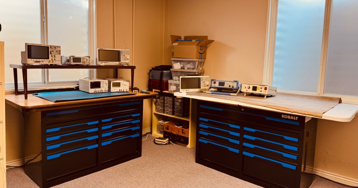
This is one reason I wrote my first book, Create Your Own EMC Troubleshooting Kit. This book lists the different equipment and probes I’ve found useful in my own lab here at the office. My current lab bench is shown in Figure 1.
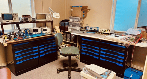
The lefthand bench includes an oscilloscope, spectrum analyzer, function generator, power supply and active load. The soldering station is just left of the power supply.
The drawers contain all the hand tools and cables. The righthand bench can be set up for custom testing and troubleshooting various EMC issues.
The picture shows a setup for conducted emissions with a spectrum analyzer and Line Impedance Stabilization Network (LISN).
The righthand drawers contain test related equipment and probes.
For the purpose of this article, let’s just distill the list down to the essential equipment recommendations.
Note that specific equipment mentioned is only an example and there are many other manufacturers that make comparable instruments. I’ll also include any upgrade options you may want to consider.
I’d suggest building your equipment in phases with radiated emissions as the first priority. Then add conducted emissions and the various immunity tests as your products require.
You’ll notice the suggestions are quite weighted heavily towards Tekbox Digital Solutions.
The reason for this is that their products are affordable, extensive and available worldwide. The U.S. distributor is Saelig Electronics in New York.
In my experience the most common EMC compliance failures include radiated emissions (RE) as overwhelmingly the top issue.
This is followed by conducted emissions (CE) for those designing power conversion.
Then comes radiated immunity (RI) and electrostatic discharge (ESD) tied for third place. Finally, electrically fast transient/burst (EFT/B).
Let’s take these tests one at a time.
Radiated Emissions
Pertinent EMC standards include CISPR 11/32 and CISPR 16 for commercial products, CISPR 25 for automotive and MIL-STD-461 for military or DO-160 for commercial aircraft.
You’ll need to construct a non-conductive table for any pre-compliance testing and for those tests requiring a ground plane, you can use aluminum foil or Tekbox’s “roll up” ground plane.
Normal characterization measurements and troubleshooting may be performed on any work bench.
Spectrum Analyzers – You’ve probably guessed that a spectrum analyzer is the instrument of choice and you’d be correct. Prices have decreased overall on these analyzers and you can purchase one for between $1k and $2k.
Most radiated emissions harmonics from power conversion, digital data or clock harmonics tend to decrease completely around 1.5 GHz, so that would generally be the highest frequency required for an analyzer.
Some military testing goes to 18 GHz, but I’ve seen very few cases where emissions occur that high.
Both Rigol and Siglent Technologies make affordable analyzers. Figure 2 shows the model I use most frequently.
You’ll want to be sure to order the tracking generator and EMI option, which provides the proper resolution bandwidths and EMI quasi-peak detector.
The tracking generator is useful for measuring coax cable and filter losses, as well as shielding effectiveness of materials.

There are a couple alternatives; oscilloscopes and real-time spectrum analyzers. Let’s discuss oscilloscopes first, as they are useful for many other measurement tasks than just EMC.
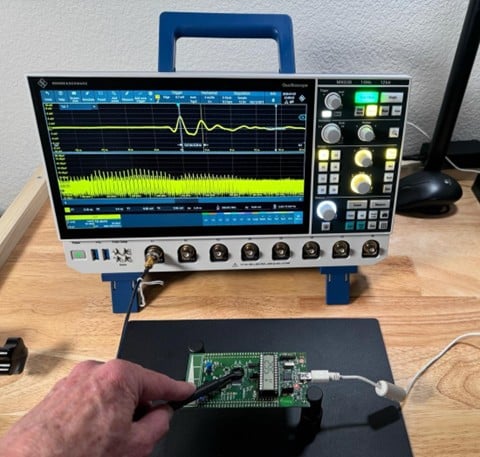
Oscilloscopes – With recent 12-bit A/D technology and Fast Fourier Transform (FFT) processing, some oscilloscopes can do double duty by displaying the time-domain as well as the frequency domain simultaneously.
Examples include the Tektronix 4/5/6-Series and Rohde & Schwarz MXO 3/4/5 Series.
I’m currently evaluating the MXO38 (8 channel, 1 GHz BW) oscilloscope and am finding it useful for general EMC troubleshooting using near field and RF current probes (Figure 3).
Real-Time Spectrum Analyzers – The most common and affordable spectrum analyzers are so-called “swept” frequency instruments.
This means that a frequency sweep from the start to stop frequencies is made, then the data is processed and finally displayed. There is “dead time” between sweeps and this makes it difficult to capture fast pulsating or intermittent EMI.
You’d have to rely on a Max Hold feature to capture and save a peak-averaged display of multiple sweeps over several seconds to have any chance of catching these fast bursts.
But then you tend to lose the finer details of the emission profile.
Real-time analyzers, on the other hand, can perform the acquisition at nearly the same speed as data is displayed, so there is very little “dead time” in between frequency sweeps.
Some analyzers can capture intermittent EMI pulses as little as 1 µs. This is very useful in displaying broadband emissions from impulsive sources like motors, relays, digital modulations and wireless transmissions.
The real-time bandwidth, that is, the largest frequency span possible for real time acquisition, is rather limited for most instruments and generally falls between 20 MHz and 40 MHz for the more affordable models and up to 100 MHz for lab-quality instruments.
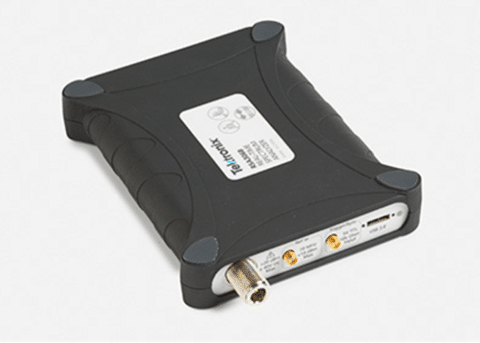
Examples of affordable USB-controlled real-time analyzers would include the Tektronix RSA306B (Figure 4) or Signal Hound BB60D.
Some benchtop instruments from Rigol or Siglent include this option for $5k to $6k.
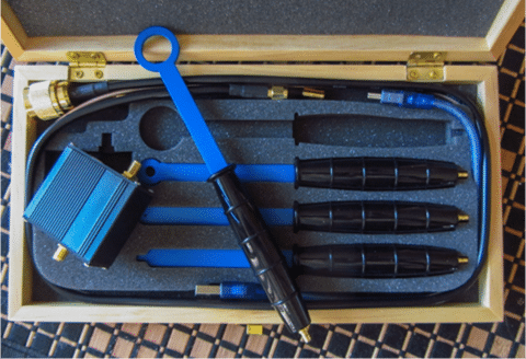
Near Field Probes – Near field probes are useful for identifying the dominant harmonic energy sources on a PC board or cable in your system.
They are usually sold in kits of four or more and connect to your spectrum analyzer or scope (set to 50Ω). Most kits will include up to three H-field probes in different loop diameters, along with an E-field probe.
Several manufacturers make these sets and some come with a broadband preamplifier of 20 dB gain to help boost the signal from the smallest loop probes.
Figure 4 shows an example of a near field probe kit from Tekbox Digital Solutions.
Enjoying this article?
Subscribe to Interference Technology for expert coverage of EMI, EMC, and signal integrity challenges—plus immediate access to new digital magazine issues.
Subscribe here →
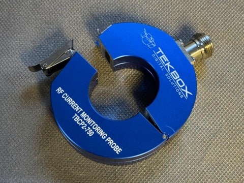
RF Current Probes – Because most radiated emissions come from attached cables, clamping an RF current probe around cables can measure the harmonic RF currents traveling along the cable.
These probes would be connected to your spectrum analyzer or scope with fast FFT set to 50Ω.
Tekbox sells a variety of these probes in various frequency ranges and you’ll want to purchase one with hinged halves that can clamp around a wire or cable. Figure 5 shows a typical RF current probe.
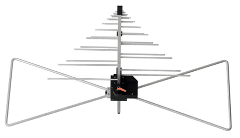
Antennas – For any pre-compliance testing, you’ll need a calibrated EMI antenna.
Several manufacturers make these and include A.H. Systems, Com-Power, ETH Lindgren. Tekbox released a full-size calibrated antenna, the TBMA8-1 that covers 30 MHz to 3000 MHz.
They also make a smaller one for pre-compliance testing, the model TBMA1C (not pictured), that covers 20 MHz to 1000 MHz at test distances of up to 3 m.
Conducted Emissions
Pertinent EMC standards include CISPR 11/32 and CISPR 16 for commercial products, MIL-STD-461 for military or DO-160 for commercial aircraft.
You’ll need to construct a metal-topped table for conducted emissions measurements according to the appropriate standard.
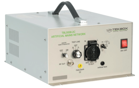
LISN – Fortunately, once you accumulate the equipment above, conducted emissions only requires a line impedance stabilization network (LISN) that is used to match the power line impedance to 50Ω for the spectrum analyzer.
For mains voltages, you’ll specify a 50 µH LISN and it can be switched to measure line and neutral. For most DC power lines (automotive and military) you’ll need a pair of 5 µH LISNs, one for the power and one for power return.
You can use your spectrum analyzer set for 150 kHz to 30 MHz (commercial) or 10 kHz to 10 MHz (military). Most spectrum analyzer manufacturers have optional measurement software as an additional purchase.
Tekbox also sells universal EMI measurement software that will work with a number of different model analyzers for both radiated and conducted emissions.
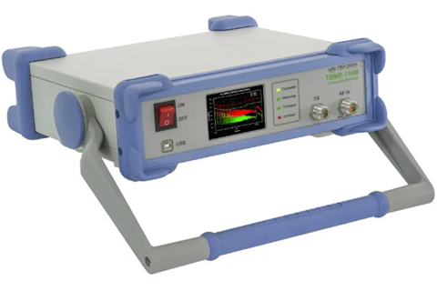
EMI Receivers – An optional upgrade would be to consider the Tekbox TBMR-110M EMI receiver (9 kHz to 110 MHz) in Figure 9 that is designed specifically for conducted emissions measurement.
The included software adds peak, average and quasi-peak detectors and can accommodate many different LISNs.
Various EMC standard limits are pre-preprogrammed into the supplied software.
Radiated Immunity
Pertinent EMC standards include IEC/EN 61000-4-3 for commercial products, MIL-STD-461 for military or DO-160 for commercial aircraft.
To perform this test according to the EMC standard requires a semi-anechoic chamber, large power amplifiers to cover the required frequency ranges and calibrated antennas that can handle high RF power.
However, for troubleshooting purposes, this can usually be performed on the benchtop.
This test is very complex and time-consuming when performed at the compliance test lab, but I find injecting strong localized RF fields directly into circuit boards or cables to be effective in isolating circuit sensitivities.
For this test you’ll need an RF signal source and possible a broadband power amplifier.
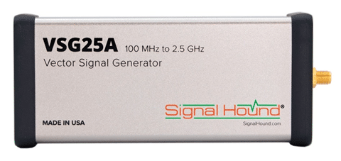
RF Signal Source – this can include the tracking generator output from a spectrum analyzer, an RF synthesizer or benchtop signal generator.
I’ve been using RF synthesizers from Windfreak Technologies and Signal Hound (Figure 10). Both these instruments can be set to 1 kHz amplitude modulation (AM) or pulse modulation.
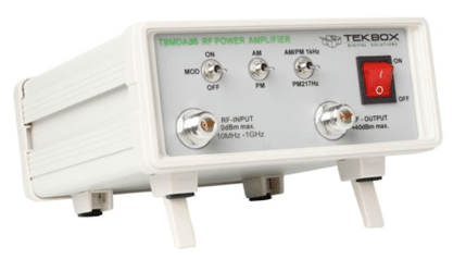
Tekbox also sells modulated RF amplifiers in various power levels that can be used with benchtop RF signal generators or the tracking generator of your analyzer.
Figure 11 shows an 8-watt modulated amplifier.
By connecting an H-field loop probe to the synthesizer output and scanning it around the circuitry on your PC board or coupling to internal cables, you can often simulate the immunity failure and commence troubleshooting.
Sometimes I find it necessary to boost the RF power using an external amplifier, such as the Tekbox TBMDA3B 8-watt, 10 MHz to 1 GHz modulated amplifier.
Electrostatic Discharge
Pertinent EMC standards include IEC/EN 61000-4-2 for commercial products, MIL-STD-461 for military or DO-160 for commercial aircraft.
You’ll need to construct a metal-topped table for conducted emissions measurements according to the appropriate standard.
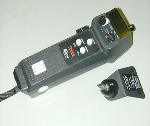
This test can easily be performed in-house using a commercial ESD simulator (Figure 12).
Several manufacturers make these and I’ve had good luck with the very affordable MinZap-15, now manufactured by M Precision Labs. Set up and perform the test according to the pertinent standard.
For troubleshooting purposes, I’ve developed a technique for tracing the path of ESD by connecting your simulator, adjusted for a safe level of 100 to 500 volts at 1 second discharges, to the sensitive points in the system.
Then by connecting the larger-sized H-field probe to your oscilloscope, you can trace the dominant path of the ESD current and help identify the component or device that’s causing the failure.
Electrically Fast Transient/Burst
Pertinent EMC standards include IEC/EN 61000-4-4 for commercial products, MIL-STD-461 for military or DO-160 for commercial aircraft.
You’ll need to construct a metal-topped table for conducted emissions measurements according to the appropriate standard.
This test requires an EFT/Burst generator. Many times, this feature comes as part of a mains power line tester that also includes mains surge and sag/dropout testing and can be pretty costly.
The pertinent standard will dictate the type of immunity test equipment.
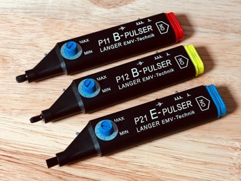
For troubleshooting purposes, Langer EMV has developed various benchtop or handheld impulse generators that can inject H-field or E-field single-shot or a 5 kHz train of pulses into your circuitry.
Figure 13 shows the small hand-held impulse injectors. The main difference in the injectors is the coupling method, either H-field or E-field.
Summary
This concludes examples of some recommended equipment and probes to complete your EMC characterization and troubleshooting setup for the most common EMC compliance failures you’ll run into.
The primary instruments to consider for radiated emissions would include a spectrum analyzer, oscilloscope, near field probes and an RF current probe. I suspect conducted emissions would be the second priority.
You can then build from there depending on whether you’d need testing for the other major tests.
Manufacturers Mentioned
- Langer EMV: https://www.langer-emv.de/en/index
- M Precision Labs: https://mprecisionlabs.com
- Rigol (North America): https://rigolna.com
- Rohde & Schwarz: https://www.rohde-schwarz.com/us/home_48230.html
- Saelig Electronics: https://www.saelig.com
- Siglent (North America): https://siglentna.com
- Signal Hound: https://signalhound.com
- Tekbox Digital Solutions: https://www.tekbox.com
- Tektronix: https://www.tek.com/en
- Windfreak Technologies: https://windfreaktech.com
- Wyatt, EMC Troubleshooting Trilogy: https://benchtopemc.com/publications/