David A. Weston, EMC Consulting, Inc., Merrickville, Ontario, Canada
INTRODUCTION
This paper shows that the antenna factor of the receiving rod antenna and the E field incident on it, from a standard source of radiation, both change when the counterpoise of the rod is either isolated from the ground plane on the table (new MIL-STD-461F set up), or connected, as per MIL-STD-461E and earlier.
The antenna factor (AF) in dB is defined as 20 log the incident E field in V/m divided by the received level in volts 20*log(E/V).
Reference 1 and Reference 2 discuss the measured antenna factor (AF) of the 41 inch (1.04m) receiving antenna with buffer. The measurements were made using different sources, such as a vertical transmission line and a second passive 1.04m monopole. It was established that both the incident E field and the AF depends on the type of source and on the connection of the monopole counterpoise to ground. MIL-STD-462 and MIL-STD-461D and E show the counterpoise extended and connected to the table via a bonding strap. This strap is often a metal sheet with the same width as the monopole counterpoise, as specified in MIL-STD-461E. One of the two configurations tested and reported in this paper was with a metal sheet bonding strap connecting the antenna counterpoise to a ground plane on the table top. MIL-STD-461F categorically states “For rod antenna measurements, electrical bonding of the counterpoise is prohibited” and this was the second configuration tested. This paper shows that measurements made with the counterpoise bonded versus not bonded results in very different received levels. MIL-STD-461F also modifies the rod antenna height so that the center point of the rod is 1.2m above the floor ground plane.
MEASUREMENT SET UP
In all measurements the receiving rod antenna cable was loaded with 28 material cores. This provides a high impedance and reduces common mode currents on the antenna cable.
The E field incident on the rod antenna, measured with the rod removed is made using a 10cm long bow tie antenna. This is connected to a low noise differential input buffer amplifier with an input resistance of 2 Megohms and an input capacitance of approximately 3pF. The wiring from bow tie to differential input adds approximately a further 2.2pF of capacitance. The differential input is converted to a single sided signal and applied to a detector with a logarithmic response. The detector allows a very high dynamic range. The output of the detector is connected to an A/D converter the output of which is translated to a digital data stream which is the input of a fiber optic driver. The electronics and battery are contained in a 6cm x 6cm x 2.5cm shielded box and the only connection to the box is the non-conductive fiber optic cable. The 10cm bow tie is connected to the box using 13cm long thin wires. Thus the perturbation in the measured E field by the measuring antenna cable and equipment is kept to a minimum. The bow tie is calibrated under a strip line antenna. Reference 1 describes the test set up in more detail.

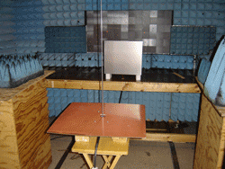
The source is a 0.44m x 0.38m metal box, representing the Equipment Under Test (EUT). The box is insulated from the ground plane and connected to the center conductor of an N type connector mounted in the table top ground plane. The front edge of the box is 10cm from the front edge of the table in a typical MIL-STD test set up. A photo of the test set up is shown in Figure 1. The signal is injected between the box and ground plane which simulates an EUT with an RF potential between the enclosure and ground plane. This potential is often the result of common mode currents on cables connected to the EUT. Even with the EUT enclosure bonded to the ground plane via a bonding strap, the RF potential may be developed when sufficient current flows to ground in the strap.
The measurements were made in a damped anechoic chamber to simulate a typical MIL-STDRE102 test. This chamber also contains localized ferrite tiles as well as absorber loads and is described in Reference 3 page 581. Although well damped above 50MHz the chamber does exhibit resonances below 50MHz. Reference 4 describes the chamber to chamber deviations for five different chambers. These range from one containing the MIL-STD-461F minimum absorber requirements to one containing hybrid absorber in a CISPR 25 compliant chamber.
MEASUREMENTS
Many commercially available 1.04m rod antennas are not calibrated but rely on a purely theoretical value based on antenna and buffer input capacitances. A test method useful from 0.01 to 5MHz, which simulates far field conditions using a plate antenna is described in Reference 1. The results using the plate antenna with a commercially available buffered rod antenna correspond well with the manufacturers published data. However when the source of radiation is a vertical transmission line, a second rod antenna or the enclosure in a MIL-STD-461 RE102 test set up the measured AF is very different from the far field and dependent on the source.
We measure both the E field incident on the rod antenna with and without bonding the counterpoise to the table as well as the AF of the rod antenna with and without counterpoise bonded. The most significant data for manufacturers of equipment is the received level with the same input signal level applied to the same source measured with and without bonding the counterpoise to the table. Here we assume that the manufacturer uses the same published far field AF of the rod antenna regardless of the test set up.

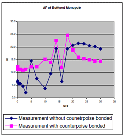
Figure 2 shows the AF measured both with and without the counterpoise bonded to the table. As seen in Reference 2 the variation in AF below 20MHz is much greater with the counterpoise not bonded. From 20MHz to 30MHz the AF with the counterpoise not bonded is 6dB higher and this is also seen in the Reference 1 test results. Reference 1 provides the AF calibrated on a free space range and the large variations seen in Figure 2 below 20MHz are missing indicating that these are due to the anechoic chamber.
The E field incident on the rod antenna is higher with the counterpoise bonded at most frequencies and this is shown in Figure 3.
Using the same buffered rod antenna the received level with the monopole counterpoise bonded is up to 18dB higher than with the counterpoise not bonded and this is shown in Figure 4.
Reference 4 describes a traditional (MIL-STD-461E) monopole antenna set up in five different chambers with different types and amounts of absorber. It also describes measurements made with a MIL-STD 461F set up. The source of radiation was either a vertical rod above the table top ground plane or a horizontal rod above the table top ground plane. From Reference 4 these resonances are attributable to ” RF current loops between the counterpoise, ground plane, ground plane to chamber connection point (wall to floor), chamber floor and the capacitive coupling back to the antenna counterpoise causes resonant conditions”. However, in Reference 2 the measurements with the counterpoises uncoupled on a free space range with no underlying ground plane shows exactly the same dip followed by peak in AF with approximately the same magnitude as References 4 and 5.
The power cords to the signal generator and spectrum analyzer in the Reference 2 measurement were the only connection to ground and the transmit rod and receive rod cables were covered in 28 material ferrite. This means that some other mechanism may at least contribute to the dip and peak.
The measurements described in Reference 4 showed the resonance effects to be greater from 10MHz to 30MHz in the MIL-STD-461E set up compared to MIL-STD-461F whereas our measurements showed the resonances to be greater in the MIL-STD-461F set up. Reference 5 describes an analysis of the MIL-STD –461E and MIL-STD-461F using a bare room without absorber. Here the prediction is that the resonant frequencies change but the amplitudes remain the same when comparing MIL-STD 461E to F. The same paper shows the room resonances with only 10cm absorber foam but no resonances from 3MHz to 30MHz with 100cm foam exhibiting only 9.5dB attenuation at 30MHz.
Reference 4 shows the received level for a vertically oriented source in a well damped chamber to be from 5 to 8dB higher for MIL-STD-461F and 5-10dB higher for the horizontally oriented source.
Whereas Reference 5 shows the theoretical received level to be 10dB higher for MIL-STD-46E versus MIL-STD-461F set up. Also Reference 2 shows the AF to be 21dB higher at 16MHz for the MIL-STD-461F set up i.e. 30dB (with delta in E field from Figure 4 ) – 8dB from Figure 2 = 21dB. This means that the received level may be 21dB lower for the MIL-STD-461F versus MIL_STD-46E test set up. The major difference in the Reference 2 set up was that the measurements were made on a free space range with and without ground planes under a transmitting rod antenna and a receiving rod antenna.
This report shows 18dB higher received level for the MIL-STD-461E set up.
Reference 2 also showed the received level from a vertical wire 10cm above a vertical ground plane was higher in the MIL-STD-461E versus MIL-STD-461F test set up. The vertical test set up simulated cables routed down a 18 inch rack. The vertical test set up simulated cables routed down a 18 inch rack.
IV. CONCLUSIONS
References 2, 5 and this report (above 20MHz) show the output level from a 1.04m rod antenna to be higher with a MIL-STD-461E test set up than MIL-STD 461F. From this report and , depending on the source of radiation, we see it may be up to 18dB lower in the MIL-STD-461F test. This is important information for EMI test personnel and manufacturers of equipment as it means that an EUT which fails RE102 from 10kHz (2MHz) to 30MHz in earlier MIL-STD-461E (and lower) measurements may now pass using the MIL-STD-461F test set up.
REFERENCES
[1] D. A. Weston Calibration of the 41 inch (1.04m) receiving monopole. Available on the EMC Consulting web site http://www.emcconsulting.com/docs/1mMono.pdf, Feb 22 2009
[2] D. A. Weston. High frequency calibration of the 41 inch (1.04m) receiving monopole with and without connecting counterpoises and with different sources. EMC Europe. Wroclaw Poland Wed. 15/09/2010
[3] Electromagnetic Compatibility Principles and Applications: D. A. Weston, Marcel Dekker 2000
[4] Improving Monopole Radiated Emission Measurement Accuracy; RF Chamber Influences, Antenna Height and Counterpoise Grounding (CISPR 25 & MIL-STD-461E vs MIL-STD-461F) Craig W Fanning. Elite Electronic Engineering Inc. © IEEE EMC Symposium on EMC 2009.
[5] Analysis of MIL-STD-461E and MIL-STD-461F RE102 Test Setup Configurations below 100MHz, D. D. Swanson. Lockheed Martin ©IEEE Symposium on EMC 2008
David A. Weston is principle EMC Engineer at EMC Consulting Inc., Merrickville, Ontario Canada. A member of IEEE and NARTE, Weston has worked full time in EMC for the last 30 years. He is author of the book “Electromagnetic Compatibility: Principles and Applications” as well as numerous papers and reports, many of which are available at emcconsultinginc.com. He studied at Croydon Technical College from 1960 to 1965.
