Self-generated EMI from DC-DC converters, as well as digital and video processing, has long plagued designers of wireless and IoT devices, especially since physical sizes have trended smaller. The broadband harmonic content often extends up through 1.5 GHz, which includes most wireless protocols, cellular LTE and GPS/GNSS bands.
One new mitigation technique I’ve been trying lately is the use of ferrite-loaded RF absorber. These come in flexible sheets of varying thickness with adhesive on one side. In my past designs of microwave modules, these could be stuck to the inside of shield covers to reduce structural resonances due to cavities.
Today, I’m starting to use them to reduce the electromagnetic field level of IC packages and flex cables. The material is made by several manufacturers, such as 3M, Parker-Chomerics, NEC and Würth Elektronik. They are primarily designed as near-field communication (NFC) shields or microwave absorbers.
Often, I need something effective in the LTE cellular frequency range of 650 to 860 MHz and it seems very few absorber materials are very effective in this range. I needed a quick way to characterize the many absorber materials I had at hand.
Unfortunately, manufacturers of these materials rarely show the absorptive properties versus frequency, but rather the permeability curves. While higher permeability materials usually mean better shielding at lower frequencies, EMC engineers are more interested in specific absorption (in dB) versus frequency, such information makes it easier to specify the correct material, depending on the application.
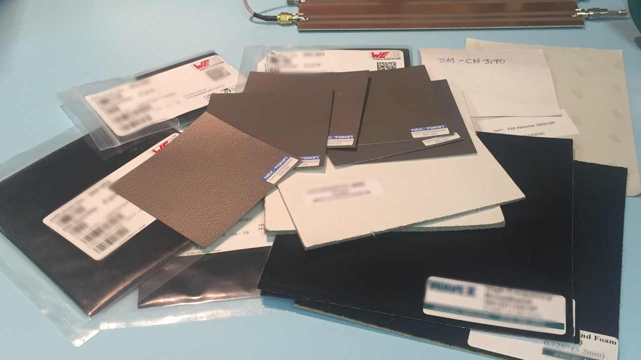
Würth Elektronik has a useful application note, ANP022, “Selection and Characteristics of WE-FSFS (Flexible Sintered Ferrite Sheet)” that shows a simple measurement technique for determining the insertion loss versus frequency. I’ve made these absorption measurements and present my results here. Figure 1 shows the tested samples.

The overall test setup was simple enough, just requiring a spectrum analyzer with a tracking generator (Siglent SSA3032X) and a 50-Ohm microstrip transmission line (Figure 2).

Once the transmission line is normalized as a straight line to eliminate basic transmission line variances with frequency, we merely place and hold the sample absorber on top of the microstrip. Generally, I measured from 100 MHz to 3.2 GHz (Figure 3).

Flexible ferrite absorber sheets are generally good for only 5 to 20 dB absorption, but let’s see what the measurements reveal.
The Arc-Tech WXA-series had excellent insertion loss of 10 to 40 dB above 1 GHz and should prove useful for applications in the cellular, GPS, and 2.4 GHz Wi-Fi bands (Figure 4).

Unfortunately, Arc-Tech closed their business and transferred the technology to others and this material is no longer available through U.S. distributors.
The Chomerics material is unique in that it has substantial absorption properties starting around 20 MHz and increasing to 20 dB insertion loss above 1 GHz. As you can see, I had to greatly expand the frequency span in order to capture the whole picture (Figure 5).

NEC has their R4N(01) material that has good absorbance in the cellular through GPS frequencies (blue trace in Figure 6).

8 × 8 cm
Case Study – Body-Worn Wireless Device
I had a chance to use this type of material on a body-worn device a few years ago. The product included cellular, Wi-Fi, Bluetooth and GPS. It also included a video camera that produced a high amount of EMI on its connecting flex cable.
During characterization measurements, I identified the DRAM, power management IC (PMIC) and video cable as the highest energy sources of interference. This self-interference was blocking reception in LTE Band 5 (and others).
Placing small squares of WAVE-X 20 absorber on top of the DRAM, PMIC and video cable (red “X”s in Figure 7) was effective in reducing the self-generated EMI primarily affecting the various cellular receiver (downlink) bands.

In Figure 8, I’m measuring the near field emissions with a small antenna at the PC board edge close to where the cellular antenna is located embedded in the case. Examining the LTE Band 5 downlink, we observe several signals that could be the cause of low receive sensitivity, including a large video harmonic (Figure 9).


Remeasuring the emissions, we see a 15-dB reduction in the video harmonic and the three narrowband signals have disappeared into the noise floor (Figure 10). The result was greatly improved reception on Band 5.

Summary
I hope this information is useful to you as you’re designing smaller wireless products, where every bit of shielding and attenuation of self-generated EMI is important. The use of small bits of ferrite-loaded absorber applied to known EMI sources appears to be a cost-effective solution to reducing self-interference affecting wireless receiver performance.
It also did not appear to affect the RF or video performance of the device. While WAVE-X 20 is no longer available in the U.S., there are other manufacturers that make equally good materials. Würth Elektronik described some alternative ways of characterizing ferrite absorber sheets, but the microstrip method was quick and easy.
References
- Würth Elektronik Applications Note ANP022, Selection and Characteristics of WE-FSFS.
- Würth Elektronik, Trilogy of Magnetics (5th Edition).
- Kenneth Wyatt, Platform Interference – Measurement and Mitigation.
