Many problems of electromagnetic compatibility and interference involve cables, which either radiate through imperfect shields and cause coupling into other cables, devices or antennas, or which receive (irradiation) external electromagnetic fields (radiated from antennas or leaked through other devices) and then cause disturbance voltages and currents potentially resulting in a malfunctioning of the system.
From the background that in modern systems cables play such a dominant role (e.g. in the automotive environment a car these days has several kilometers of cables) it is crucial that already in the design process of electromagnetic systems such coupling / radiation / irradiation effects involving cables are taken into account from an EMC perspective. A simple example for this is shown in Figure 1 (cable bundle inside a car).
Figure 1. Generic car model including a cable path.
Shortened design cycles do not leave time to perform extensive measurements and correct the system, rather designs are done using CAD without physical models and only final verification / compliance measurements are done. To this end, we review in this article the solution of combined electromagnetic field / cable problems and their numerical solution with computer simulation techniques. All the formulations and examples presented in this paper are based on FEKO [1], which in its Suite 6.1 release provides such integrated cable modeling facilities in both the computational kernel and the user interface (traditionally FEKO has been a field computation package with interfaces to various other cable modeling codes).
COMPUTATION OF ELECTROMAGNETIC FIELDS
The central aspect of modeling both the radiation and irradiation of cables in a complex environment (e.g. Figure 1 cable in an automotive environment) is, besides the cable modeling as such, the ability to compute electromagnetic fields.
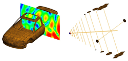
An example of such an electromagnetic field problem (without cable) is shown in Figure 2 where a log-per EMC measurement antenna is radiating and exciting electromagnetic fields which interact with the device under test (here a car) and the near-field depicted in this figure shows the resulting interference pattern.
Figure 2. Log-per antenna radiating electromagnetic fields which interact with the device under test (here a car body) and cause an interference pattern.
To solve such problems, FEKO is based on the Method of Moments (MoM) [2]. Metallic surfaces are discretized into triangular patch elements and wires are meshed into segments (with mesh elements being small compared to the wavelength), and then with certain basis functions the currents and charges are represented on this mesh with unknown complex coefficients. A procedure similar to the classic implementation of Rao, Wilton, and Glisson (RWG) in [3] is followed to obtain these unknown coefficients by solving a system of linear equations, which for open bodies (i.e. with holes / apertures) is derived from the electric field integral equation.
As compared to this traditional formulation (the RWG basis functions celebrate their 30th birthday this year), many improvements have been made over the years. For instance, in FEKO not only metallic but also dielectric bodies can be handled, special formulations for shielding from finite conducting material are available, a fast frequency sweep based on adaptive interpolation techniques, using current computer technologies like multi-core, parallel cluster processing or also GPU computing, or special solution techniques exist for integrated windscreen antennas [4] (common in many modern cars).
Despite this, one might find the solution of high frequency problems with the MoM is too challenging even on modern computers (due to memory and run-time constraints). To overcome this problem, we have hybridized the MoM with special high frequency techniques (such as Physical Optics or Diffraction Theory), and have accelerated the MoM leading to the Multilevel Fast Multiple Method (MLFMM) [5] or using Adaptive Cross Approximation (ACA) [6]. For complex problems involving multiple media also a full bi-directional FEM/MoM hybrid method is available [7] (FEM = Finite Element Method).
SOLUTION OF COMPLEX CABLE PROBLEMS
Multi-Conductor Transmission Line (MTL) Theory
In principle, the methods presented in the previous section (MoM, MLFMM, FEM etc.) can solve arbitrary problems, which also include cables. For such a solution, then all the details would have to be included in the model and discretized (e.g. multiple wires in a cable bundle, all the dielectric insulations, shields etc.). For practical problems, this is not possible (for simple problems it is possible and will be done later for some validation examples). In the following we give a review of the Multi-Conductor Transmission Line (MTL) Theory which can solve complex cable problems very efficiently.
In many ways transmission line theory bridges the gap between full wave solutions and basic circuit theory. As such, the phenomenon of wave propagation on transmission lines can be approached from an extension of circuit theory or from a specialization of Maxwell’s equations.
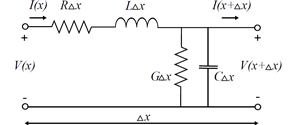
As shown in Figure 3 an incremental length of a two-conductor transmission line can be described by the Telegrapher’s equations [8]
where x denotes the longitudinal direction and parameters Z and Y are the per unit length impedance and admittance parameters of the line
Z = jωL + R
Y = jωC + G.
Figure 3. Distributed parameters for an incremental length of transmission line.
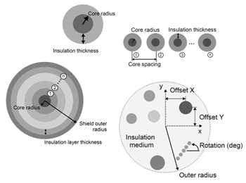
As a generalization to the two-conductor system, a multi-conductor transmission line model is simply a distributed parameter network for an arbitrary cable cross section (see Figure 4) where the voltages and currents can vary in magnitude and in phase over its length.
Figure 4. Selection of some of the cable types supported in FEKO.
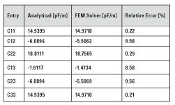
Table 1. Transmission line per unit length capacitance matrix entries for three widely spaced conductors above ground: Comparison of analytical values with the numerical static FEM solution.
Per Unit Length Cable Parameters
The per unit length parameters of inductance, capacitance, resistance and conductance are essential ingredients in the determination of transmission line voltages and currents from the solution of the transmission line equations. All of the cross sectional dimension information about a specific line is contained in these parameters.
Under the fundamental transverse electromagnetic field structure assumption, the per unit length parameters of inductance, capacitance, and conductance are determined as a static solution to Laplace’s equation ∇2 Φ(x,y)=0 in the two-dimensional cross sectional (x,y) plane of the line. The determination of the per unit length parameters can be simple or very difficult depending on whether the cross sections of the conductors are circular or rectangular, and whether the conductors are surrounded by a homogeneous or an inhomogeneous dielectric medium.
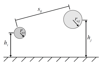
Figure 5. Parameters for the computation of the per unit length inductances of widely separated wires above a ground plane.
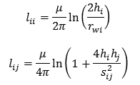
In fact, there are very few transmission lines for which the cross sectional fields can be solved analytically to give simple formulas for the per unit length parameters. To illustrate, the self-inductance and mutual inductance terms of n widely spaced cores above an infinite ground (see Figure 5) can be derived as [9]
where rwi is the wire radius, hi is the wire height above ground and sij is the center to center spacing between wires. If however these cores are surrounded by an insulation medium or the separation is not wide, one has no alternative but to employ approximate, numerical methods. In FEKO a 2D static FEM solver to Laplace’s equation is used. Table 1 compares the analytic to the numerical per unit length capacitance matrix entries for 3 wires above ground (rw1=rw3=1.0 mm, rw2 = 1.5 mm, h1=h3=52 mm, h2=50 mm, s12=s23=15.13 mm, s13=30 mm. The 2D FEM solution is based on minimizing the stored field energy per unit length. The self-capacitance matrix entries are a direct function of the total energy in the system, and hence these terms agree very well with those of the analytic prediction. The mutual capacitance matrix entries are derived from the FEM solution (integration over -∇Φ) and as such use a lower order approximation, also explaining the larger differences between the analytic and numerical solutions.
Coupling of External Fields into Cables
Transmission lines can be excited by electromagnetic fields where their effect is to induce currents and voltages on the line and in the load impedances at the ends. There are three approaches for describing the coupling of an external field to a line using transmission line theory: the Taylor approach [10], the Agrawal method [11] and the Rashidi method [12]. Each of these coupling formulations gives the same response for the transmission line, although there are subtle differences in these techniques.
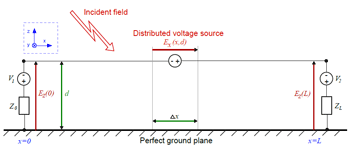
In FEKO the coupling of external fields into cables is considered with the scattered voltage formulation described by Agrawal. The problem can be considered to be an electromagnetic scattering process in which the tangential incident electric field along the conductors can be viewed as distributed voltage sources exciting the transmission line (see Figure 6).
Figure 6. Field excitation of a transmission line using only voltage sources (Agrawal method)
Treatment of Cable Shields
In transmission line theory, the conductors in a cable bundle can be grouped into outer and inner circuits, each of which is coupled with a mutual conductor called a shield. The outer and inner circuits are completely separated by this shield, except that they are connected by current- and voltage-controlled sources (there should be no other connection between outer and inner circuits). The shield coupling parameters defining these controlled sources are termed transfer impedance ZT and transfer admittance YT, which may be formally defined as follows
where Is, Vs and Ii, Vi are the currents and voltages on the outer shield and inner conductor of the separate circuits. Both ZT and YT are basically dependent on the geometric and physical properties of the conductor system and as such are valid for both solid and braided shields.
For a solid tubular shield, the Schelkunoff model [13] is typically used
where D=[I1 (γb) K1 (γa)-I1 (γa) K1 (γb)] and γ=√jωμ(σ+jωε), while a and b are the inner and outer radius of the shield respectively. The electrostatic shielding is much greater than the magnetostatic shielding, and as a result, the transfer impedance term dominates at low frequencies. This fact has led many investigators to neglect the transfer admittance term in EMC coupling problems.
For braided shields as in Figure 7, the model proposed by Kley [14] is very popular. The coupling mechanism giving rise to the transfer impedance and admittance are enhanced, due to the field penetration through the shield apertures. At low frequencies, the electrostatic shielding of the braid is much better than the magnetic field shielding (YT<<ZT). As the frequency increases, both the E and H fields are able to penetrate the braid apertures, and the induced effects on the inner conductor from both field components can be of the same order of magnitude, in which case the transfer admittance cannot be ignored.
Figure 7. Braided cable showing different weave parameters.
COMBINING FIELD AND CABLE SIMULATION
The standard field-cable coupling formulation is a two-step procedure [11, 15].
For cable irradiation problems:
1. Solve the external problem with radiation sources and all structures except the cable bundles. Specifically, evaluate the electromagnetic near field along all cable bundle paths.
2. Use the calculated near field values as distributed sources together with multi-conductor transmission line theory, to solve the induced currents on the constituent wires in the bundles. Transmission line properties (L, C, R, G-matrices) used in the solution are evaluated numerically along the cable paths, based on local geometry. For shielded cables, near field values are used as distributed sources for the outside transmission line problem. The resulting current solution on the outside of the shield is then converted via the transfer impedance and admittance to distributed sources, which are then employed as excitation for the interior multi-conductor transmission line problem.
For cable radiation problems:
1. Based on specified circuit sources together with multi-conductor transmission line theory, solve the excited currents on the constituent wires in the bundles. Transmission line properties used in the solution are evaluated numerically along the cable paths, based on local geometry. For shielded cables, employ the transfer impedance and admittance bi-directionally similarly as in the irradiation case.
2. Solve the external problem with the excited cable bundle currents as impressed current sources replacing the cable bundles.
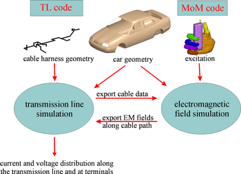
These two steps for radiation or irradiation can either be done by two codes which have an interface for the data exchange (e.g. interfaces between FEKO and CableMod or CRIPTE as cable modeling tools, see Figure 8 for a flow chart), or can also be integrated into one code (such as FEKO Suite 6.1) allowing for a better user experience (one common user interface, no data export / import).
Figure 8. Combination of a transmission line (TL) and method of moments (MoM) code for solving the irradiation problem.
This standard MTL approach does pose some challenges, e.g. that common mode currents and radiation loss cannot be modeled. One of the main limitations is that a cable bundle must run close to a conducting surface, typically with less than λ/5 spacing [16]. The reason for this restriction is that the formulation is derived assuming a TM field distribution in the vicinity of the bundle and conducting surface, which is valid only when the gap is small. Stated differently, when there is no external conducting surface close to the cable path the external problem cannot be solved using cable theory.
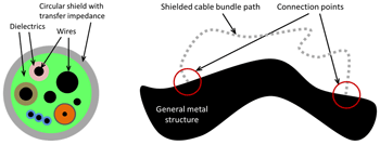
In FEKO a MoM/MTL combined approach was introduced to avoid this problem. As shown in Figure 9, a shielded cable bundle may now follow an arbitrary path, with the ends connected at two points on a metal structure. The method relies on the assumption that the exterior (structure and shield) and interior (cable bundle) problems only couple weakly through the transfer impedance. A very similar approach has been proposed in [17].
Figure 9. Example of permissible cross section and schematic cable path setup in the MoM/MTL combined approach (cable far away from ground).
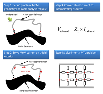
Figure 10. Step-by-step analysis method for shielded cable bundles following arbitrary paths, terminating on a metal structure.
The steps of the irradiating case of the analysis method are shown in Figure 10 and are as follows:
1. Set up the problem geometry and cable analysis request. The metallic structure will be meshed with triangular elements. The exterior of the cable path will be included in the full-wave analysis with the MoM using thin shell wire segment elements of which the radius, thickness and material properties are the same as that of the shield.
2. Solve the external MoM system to obtain the shield (wire segment) exterior current. The MoM solution yields the total current flowing on the shield exterior.
3. Use the transfer impedance of the shield to convert the exterior shield current to a distributed voltage source exciting the multi-conductor transmission line interior problem.
4. Solve the internal problem using multi-conductor transmission line circuit analysis.
In a similar manner also the radiating case can be dealt with.
VALIDATION AND APPLICATION EXAMPLES
Although the techniques presented in this paper can be applied to complex real-world problems (e.g. cable harness running in a car), we present in the following rather simple validation and application examples. These examples have the advantage that full wave MoM solutions (i.e. discretizing the cable into MoM wire segments) exist as reference to compare to the combined MoM/MTL technique, or measurements / reference results from literature based on other techniques or other implementations available.
RG58 Coaxial Cable Close to Monopole Antenna (Irradiation)
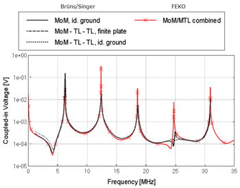
A monopole antenna of 10 m height is fed by an input power of 10 W and is radiating in the neighborhood of an RG58 coaxial cable which forms a U-shaped loop of length 24.24 m. The axis of the cable is assumed to be 10 mm above a PEC ground with both shield ends short-circuited to ground. The coaxial core is terminated in 50 Ω to the shield and the shield transfer impedance is available from a measurement database. The frequency range extends from 1 MHz to 35 MHz. Figure 11 shows the configuration setup while Figure 12 compares the FEKO solution to reference results [18] for the voltage at the cable end closest to the antenna (Port 1). The results from [18] are based on a standard MTL / MoM combination which is only applicable to cables running close to ground, which is the case here, thus one can consider [18] as independent reference here.
Figure 11. FEKO model of a monopole antenna close to an RG58 coaxial cable above ground.
Figure 12. Magnitude of the induced voltages at the cable end closest to the antenna.
Single L-Shaped Conductor Line above Finite Ground (Irradiation)
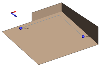
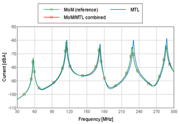
In Figure 13, the geometry setup of a single wire cable (radius 2 mm) over a finite size ground plane with side walls is shown. Both ports are terminated in high impedance (15 kΩ). The excitation is by a right-hand circular polarized plane wave (magnitude 3 V/m; polarization angle 450). Figure 14 compares the induced current in the load at CCend using different methods available in FEKO (full MoM reference solution in green, MoM for the plate and standard MTL for the cable in blue, and the combined MoM/MTL method where the outer cable problem is also solved with MoM in red). All these results agree very well. The two MTL results agree very well to the standalone MoM result, which can be considered a reference solution (see our comments above, such a full wave MoM solution is accurate, but can be obtained only for simple configurations due to the effort with regards to memory and run-time).
Figure 13. FEKO model for an L-shaped single conductor cable over a ground shape.
Figure 14. Magnitude of the induced current in the load at CCend.
Shielded RG58 Cable above Ground Plane with Gap (Radiation)
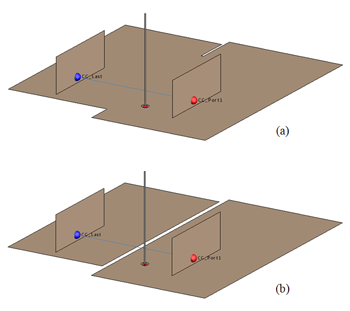
In this example radiation from an RG58 C/U coaxial cable to a nearby antenna is computed. Two different ground plane arrangements were investigated (see Figure 15): (a) common ground between the cable source at CC_Port1 and load at CC_Last; (b) separate grounds (2 cm apart) between the cable source and load leaving a gap.
Figure 15. FEKO model for the geometry setup of a shielded RG58 cable above different ground plane arrangements: (a) one single ground plane under the cable and (b) two separated ground planes with a slot in-between.
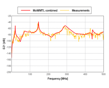
Figure 16. S-parameter comparison for shielded RG58 cable above common ground plane, configuration (a).
Figure 17. S-parameter comparison for shielded RG58 cable above ground plane with gap, configuration (b).
The presence of separate ground structures for the configuration (b) restricts the usage of standard MTL techniques. The outer problem can no longer be solved using cable theory as there is no return path for the current to flow below the cable path. However, when using the unique MoM/MTL combined approach in FEKO, the current on the cable shield exterior is solved using MoM where there is no limitation regarding the cable path w.r.t. the surrounding geometry.
As this is not a single wire but a real RG 58 cable, a simple MoM reference solution without involving MTL is not possible here. Also as explained the standard MTL (without MoM combination) cannot be used, thus the only available validation here are measurement results (obtained independently from our calculations). Figures 16 and 17 compare the FEKO MoM/MTL combined approach to measurement results for the two different ground plane arrangements, and for both configurations (with and without gap in the ground plane) the agreement is again very good.
CONCLUSIONS
We gave an overview on how modern electromagnetic simulation techniques can handle combined field / cable problems, both for radiation and irradiation. The different approaches to handle such problems were summarized, and we introduced in particular a combination of MTL and MoM where the outer transmission line problem (shield and ground) is solved with MoM which enables one to solve cable problems where there is no distinct nearby ground plane (e.g. ground far away, or ground with holes / slots).
Several examples were presented and solved with the computer code FEKO, demonstrating the successful application of these techniques.
REFERENCES
[1] FEKO, www.feko.info
[2] R.F. Harrington, “Field Computation by Moment Methods,” Macmillan Company, New York, 1968.
[3] S.M. Rao, D.R. Wilton, and A.W. Glisson, “Electromagnetic Scattering by Surfaces of Arbitrary Shape,” IEEE Transactions on Antennas and Propagation, Vol. 30 No. 3 May 1982: 409-418. Print.
[4] U. Jakobus, and M. Schoeman, “Effiziente Analyse von Integrierten Scheibenantennen,“ 5. GMM Fachtagung Elektromagnetische Verträglichkeit in der Kfz-Technik, BMW-Welt München, Oct. 2009. Print.
[5] U. Jakobus, J. van Tonder, and M. Schoeman, “Advanced EMC Modeling by Means of a Parallel MLFMM and Coupling with Network Theory,” IEEE International Symposium on Electromagnetic Compatibility, Detroit, Mich. USA Jul. 2008. Print.
[6] S. Rjasanow, and O. Steinbach, “The Fast Solution of Boundary Integral Equations,” Springer, New York, 2007.
[7] F.J.C. Meyer, D.B. Davidson, U. Jakobus, and M. Stuchly, “Human Exposure Assessment in the Near Field of GSM Base Station Antennas using a Hybrid Finite Element / Method of Moments Technique,” IEEE Transactions on Biomedical Engineering, Vol. 50 Feb. 2003: 224-233. Print.
[8] F. Tesche, M. Ianoz, and T. Karlsson, “EMC Analysis Methods and Computational Models,” Wiley-Interscience, 1997.
[9] C. Paul, “Analysis of Multiconductor Transmission Lines,” Wiley-Interscience, Second Ed., 2008.
[10] C.D. Taylor, R.S. Satterwhite, and C.W. Harrison, Jr., “The Response of a Terminated Two-Wire Transmission Line Excited by a Nonuniform Electromagnetic Field,” IEEE Transactions on Antennas and Propagation, Vol. AP-13 No. 6 Nov. 1965: 987-989. Print.
[11] A.K. Agrawal, H.J. Price, and S.H Gurbaxani, “Transient Response of Multiconductor Transmission Lines Excited by a Nonuniform Electromagnetic Field,” IEEE Transactions on Electromagnetic Compatibility, Vol. EMC-22 No. 2 May 1980: 119-129. Print.
[12] F. Rashidi, “Formulation of Field-to-Transmission Line Coupling Equations in Terms of Magnetic Excitation Field,” IEEE Transactions on Electromagnetic Compatibility, Vol. EMC-35, No. 3 Aug. 1993: 404-407. Print.
[13] S.A. Schelkunoff, “The Electromagnetic Theory of Coaxial Transmission Lines and Cylindrical Shields,” Bell Syst. Tech. Journal, Vol. 13, 1934: 522-579. Print.
[14] T. Kley, “Optimierte Kabelschirme – Theorie und Messung,” Ph.D. dissertation, Swiss Fed. Inst. Tech., Zürich, 1991.
[15] C.A. Nucci, and F. Rachidi, “On the Contribution of the Electromagnetic Field Components in Field-to-Transmission Line Interaction,” IEEE Transactions on Electromagnetic Compatibility, Vol. 37 Nov. 1995: 505-508. Print.
[16] G. Andrieu, L. Kone, F. Bocquet, B. Demoulin, and J.-P. Parmantier, “Multiconductor Reduction Technique for Modeling Common-Mode Currents on Cable Bundles at High Frequency for Automotive Applications,” IEEE Transactions on Electromagnetic Compatibility, Vol. 50 Feb. 2008: 175-184. Print.
[17] S. Helmers, H.-F. Harms, and H.-K. Gonschorek, “Analyzing Electromagnetic Pulse Coupling by Combining TLT, MoM, and GTD/UTD,” IEEE Transactions on Electromagnetic Compatibility, Vol. 41 Nov. 1999: 431-435.
[18] H.-D. Brüns, and H. Singer, “Computation of Interference in Cables Close to Metal Surfaces,” IEEE International Symposium on EMC, Denver, Col. 1998: 981-986. Print.
Marlize Schoeman received the B.Eng-M.Sc.Eng and PhD degrees in Electronic and Computer Engineering from the University of Stellenbosch, South Africa, in 2003 and 2006, respectively. There she has been involved with research activities concerning computational electromagnetics and rational function interpolation and approximation techniques. Since July 2006 she has been with EM Software & Systems, Stellenbosch, South Africa, where she is doing research and development on the kernel of the FEKO code.
Ulrich Jakobus received the diploma, PhD and Habilitation (venia legendi) degrees in Electrical Engineering from the University of Stuttgart, Germany, in 1991, 1994, and 1997, respectively. There he has been actively involved in research on numerical techniques for the solution of electromagnetic problems with special emphasis on EMC, and this research lead to the computer code FEKO. Since October 2000 he is with EM Software & Systems, Stellenbosch, South Africa, with the roles of Director, FEKO Product Manager, and team leader of the FEKO kernel team.


