IoT products are often seen as an entry-level product for many PCB designers, and they require application and protocol development. It’s no wonder so many engineers and design firms market themselves as IoT solutions providers.
Developing an embedded application and throwing it on a microcontroller is all well and good, but you’ll never deploy thousands or millions of embedded devices unless they can comply with EMC regulations.
In my time doing design reviews for companies and individual designers, I have found five common mistakes that designers make in IoT products.
Some of this comes from blindly following datasheets or application notes without understanding context, and some of it simply stems from lack of PCB design experience.
Let’s jump in and discuss some of these common mistakes in IoT products.
MISTAKE #1: THAT MICROCONTROLLER IS HUGE
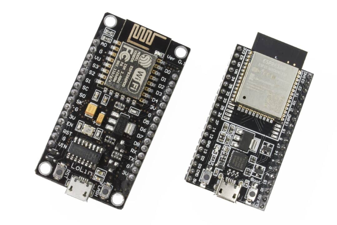
An excessively large or overpowered microcontroller is one common mistake I see. This is especially true among new designers, who will typically use the STM32 or ESP32 module they learned in university courses.
The use of the ESP32 modules or an ATmega MCU is understandable, especially in module format; the module contains a built-in antenna that most IoT products would typically need.
The problem with this is that these microcontrollers typically have many unused pins and features that the device does not need.
Designers then typically increase their power handling capability through larger regulators or switching regulators, which may create an EMC challenge if not done correctly.
A more thorough look through the supply chain for a smaller microcontroller leads to an easier, less complex system design.
One other common reason that microcontroller modules make their way into IoT products is because the modules are pre-certified, including by the FCC, or they may have a CE marking.
Unfortunately, simply building an IoT product around a pre-certified module does not constitute EMC compliance for most products. This has been discussed in this publication in a previous post.
MISTAKE #2: CONNECTORS NEAR AN ANTENNA
This next mistake is sometimes a symptom of having an excessively large microcontroller, where too many components are packed into small real estate.
Placing a connector near an antenna, such as large vertical pin headers, can alter the radiation pattern of the antenna and reduce the gain.
A better option is to use a different location for the connector so that it does not interfere with the radiation pattern.
If this is not possible, there are other connector options which are lower profile, especially compared to MCUs in module format:
- ZIF connectors for FPC cables
- Mezzanine connectors, also for FPCs
- Depopulated headers for attaching flying leads
- Surface mount solder pads, also for flying leads
Enjoying this article?
Subscribe to Interference Technology for expert coverage of EMI, EMC, and signal integrity challenges—plus immediate access to new digital magazine issues.
Subscribe here →
MISTAKE #3: BASIC CIRCUIT PROTECTION IS MISSING
IoT products are not just wireless devices. They will need to interface with other devices using cabling.
IoT products deployed in the field might also have hot-plug-gable cabling so that there is no downtime during servicing.
Similarly, not all IoT products are battery powered and instead will receive their power through a cable and connector.
In both cases, some basic circuit protection is needed at the circuit level and in the PCB layout.
With regards to circuitry, this could involve placing any of the following components or circuits for circuit protection:
- Reverse polarity protection
- Unidirectional or bidirectional TVS diodes
- Surge suppressor circuits
- Small gas discharge tubes
- Resettable fuses
- MOVs, NTC thermistors, or fusible resistors
These circuit protection measures address issues like ESD, surges, inverted power connections, and even lightning.
From the EMC perspective, additional measures used alongside circuit protection include filtering, particularly on devices which use AC power.
MISTAKE #4: POWER IN MIXED SIGNAL DEVICES
Another potential problem found in many IoT devices comes from the fact that they are mixed signal devices.
IoT products are typically used for some kind of sensor data capture, onboard processing, and transmission back to a cloud platform.
When mixed signal devices are used in a PCB, the subject of mixed signal grounding and power often comes up. Some of the practices that can lead to EMI failure include:
- Splitting ground planes, which creates a dipole antenna
- Reconnecting split ground planes with a ferrite or ferrite-capacitor circuit
- Using ferrites as filters between digital and analog power domains
- Overlapping analog and digital power rails
While not exclusive to IoT products, these problems tend to be common due to the aggressive form factors and mixed signal functions in many IoT products.
MISTAKE #5: CONNECTOR PINOUTS
The last mistake I would like to highlight relates to connector pinouts.
Many IoT devices do not use a standardized connector and cable pair to transmit and receive data. At minimum, there may be a cable assembly that aggregates power and data into the same interconnect.
The connector pinout on the PCB and the connected wiring can be a source of emissions, susceptibility, and/or crosstalk between signals.
The simplest way to improve SI and EMI in a connector pinout is to include extra pins dedicated to grounds. These can be interleaved between the signal lines. This is acceptable particularly in the case of single-ended signals which require a ground reference, including when routed out over a cable.
In small IoT products, this is difficult because space is at a premium, and there may not be room to expand connector footprints just for additional ground pins.
Also, ground pins are not the only solution to crosstalk or EMI. Chokes, filter circuits, or possibly shielding on the cable assembly may be used to solve specific EMI problems.
It’s also possible to use a differential buffer or line driver to transmit signals over twisted pair, which tends to have lower emissions and susceptibility.