Editor’s note: This question was asked in response to Interference Technology’s recent webinar by Keith Armstrong. To view the webinar, click here.
Question: What are the slew rates in digital circuits these days and what kinds of frequency spectra are generated?
Answer: The slew rates of the digital signals generated by integrated circuits tend to increase as the silicon feature sizes used in their chips tends to decrease according to Moore’s Law.
For example, HC logic chips when originally introduced in the 1980s tended to have output pins with rise and fall times measured in a few nanoseconds (ns). But the exact same IC part numbers purchased in 2012 have rise and fall times under 0.5ns. When PCI Express was first introduced nearly 10 years ago, the typical rise and fall times of its IC’s output pins were 100 picoseconds (ps), but now they are significantly less.
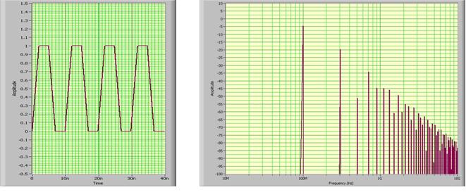
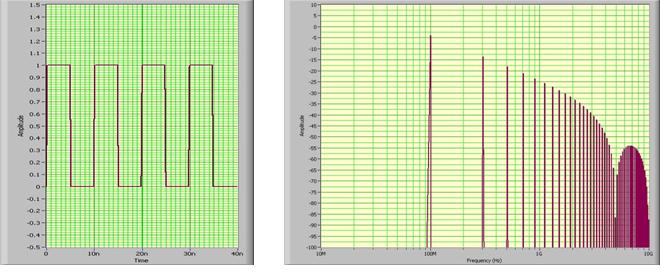
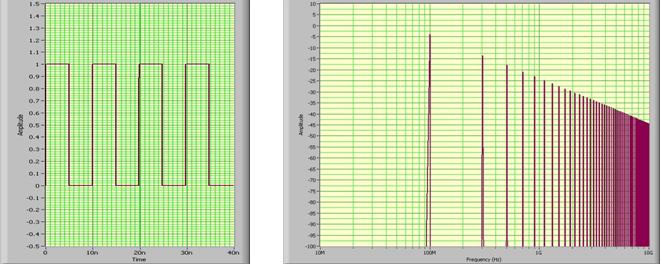
The usual way of deriving the frequency spectrum associated with a square wave having a certain rise time (tr)is to understand that the spectrum of a square wave only contains odd harmonics of the fundamental, and their amplitude reduces at the rate of 20dB/decade of frequency. However, above a frequency that is calculated as 1/ptr, the harmonics reduce as frequency increases at the rate of 40dB/decade. Here is a figure, taken from one of my PCB EMC training courses, showing how the envelope of the frequency spectrum changes for a 100MHz clock with different rise/fall times.
Below are simulations corresponding to the above figure, frequency range 10MHz -10GHz.
100MHz clock with 2ns rise/fall times
100MHz clock with 0.2ns rise/fall times
100MHz clock with 20ps rise/fall times
2ns is where we were in the 1990s, these days we are generally around 0.2ns but the 22nm chips are probably faster than that. In a few years’ time we will have to deal with 20ps rise/fall times.
The above is fine when we know what the value of tr is, but the data sheets for ICs only state the maximum value and the real values are always less than this, and will reduce as time goes on and the silicon chips inside them are replaced by die shrunk versions (according to Moore’s Law).
It seems the only reliable way to determine the rise/fall times and/or frequency spectrum is to measure one and calculate the other based on the 20dB/40dB per decade frequency breakpoint being at 1/ptr.
To measure rise/fall times, it is easiest to equip our PCBs with some of its ICs’ digital output pins connected directly to miniature coaxial connectors of a type that match our oscilloscope’s probes, and use an oscilloscope and probe set that has a bandwidth much greater than we expect. So, for example, if we want to be able to measure rise/fall times of 0.2ns, we must use a ‘scope and probe bandwidth that is at least 3GHz.
But generally, when I’m asked to help solve EMC problems, the PCBs aren’t fitted with miniature coaxial connectors in the appropriate places, so I use a small close-field magnetic loop probe and hold it against the body of the ICs, measuring its output with a spectrum analyzer having more than enough bandwidth (e.g. 3GHz in the case of 0.2ns rise/fall time).
When we hold a close-field loop probe very close to an IC or PCB trace, we pick up some of the differential-mode (DM) fields that are the actual signals or power currents, so these measurements don’t indicate an EMC problem. As I said in my webinar, it’s when the probe picks up significant levels of noise far from the ICs, traces, etc., that we have problems; because this shows that we have a poor EMC design that permits stray currents to flow in large loops – usually common-mode (CM) noise.
With a small enough probe, we can move around the body of an IC and see the spectrum of the signals used in its core logic in one area, and the spectrum of the output driver signals in another.
The advantage of using the “small close-field loop probe held against the body of the IC” method is that we can see the frequency spectra of the IC’s digital operations directly – which is what we need to know for our EMC design techniques. And we don’t need to worry about using coaxial probes. (Remember: any ‘scope probe that has a flying ground lead is useless for measuring above a few 100MHz.)
Actually, we can also use a “pin probe”, which has a small capacitor in series in its tip and no ground lead at all, to connect directly into a spectrum analyzer and determine the spectrum associated with each output pin.
Please note that the ever-continuing die shrinks (Moore’s Law) have two implications:
1) EMC design is always changing, becoming more difficult as the noise emissions frequencies increase, so cost-effective design techniques are always changing, year on year.
2) Serially-manufactured products that comply when tested one year, might fail in two or more years’ time when all of its digital ICs are using new die-shrunk silicon chips. For this reason, many volume manufacturers have their own EMC test departments that test each and every one of their products that are in serial manufacture, at least once per year.
So, to design products that will pass their EMC tests in serial manufacturer at least 2 years from now, we should expect the rise/fall times we measure to get shorter, and their frequency spectra to get higher, and design accordingly. Often this means that our bosses complain that we have over-engineered when our new design passes its EMC tests with very good margins – but we have to explain to them that this is to ensure that we don’t have to re-design them when the chips suffer their next die-shrinks, as they will within the next two years.
The core logic of microprocessors and FPGAs has always switched much faster than their output drivers, and – for example – Xilinx Vertex 2 FPGAs used to have power supply transient currents on their core logic rails that had durations of 15ps (i.e. rise up and fall down in 15ps)! Since Vertex 2 was about 5 die-shrinks ago (current Xilinx FPGAs are Vertex 7) we should expect the core logic power supply noise currents to have much shorter rise/fall times, i.e. a bandwidth much greater than 20GHz. So, as well as signal rise and fall times, we need to design our power rails accordingly so as not to suffer excessive emissions from them.
– Keith Armstrong


