
Conducted emissions failures, across commercial, industrial, automotive, and defense sectors, remain consistently ranked among the top three most common EMC test failures.
This is somewhat surprising, given that filtering techniques are well understood and widely used by design engineers. Yet, many products continue to struggle during conducted emissions testing.
This raises an important question: Are conducted emissions easy to pass? If so, what prevents engineers from implementing effective solutions, such as filters, early in the design phase?
This article focuses on one often-overlooked contributor to conducted emissions failures: common-mode current paths created by parasitic capacitance in the test setup or in a system.
Through practical case studies, we demonstrate how test configuration, grounding, and unintended coupling paths can significantly affect results, and what design engineers can do to mitigate these issues.
Differential Mode vs. Common Mode in Conducted Emissions
Conducted emissions tests are typically performed using Line Impedance Stabilization Networks (LISNs), which measure noise present on power lines.
Unlike current-probe measurements, LISNs capture both differential-mode (DM)and common-mode (CM) noise.
Differential-mode noise generally has a well-defined return path, making it relatively straightforward to address. Solutions such as:
- π-filters (C–L–C),
- Optimized DC-link layouts, or
- Improved decoupling capacitors
are often effective in reducing DM noise.
Common-mode noise, however, presents a greater challenge. Although extensively discussed in EMC literature, CM noise often feels like “black magic” in practice because its return path is not always obvious.
This lack of visibility frequently leads to ineffective mitigation strategies.
Case Study 1: When a Certified Charger Fails the Product Test
A robotic manufacturer encountered a puzzling problem. An off-the-shelf battery charger (bearing valid CE and FCC markings) passed conducted emissions testing with good margin.
Yet, when integrated into the robot, the product failed conducted emissions testing in the EMC lab.
At first glance, it was tempting to suspect incorrect or fraudulent compliance markings on the charger.
However, further investigation revealed a different root cause.
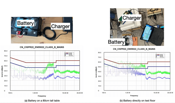
When tested independently, both the charger and battery were placed on an 80 cm-high insulating support above the test ground plane, per standard conducted emissions test setups.
In this configuration, the charger passed comfortably. During the product EMC testing, however, the robot was floor-standing.
While the charger remained on the 80 cm support, the battery was positioned inside the robot, meaning only 10–20 cm above the ground plane, reflecting the real installation.
Repeating the test with the battery lowered to approximately 10 cm above the ground plane resulted in conducted emissions failure, despite using the same charger and battery.
The only change was the physical height of the battery relative to the ground plane. The results of both setups are shown in Figure 1.
The manufacturer’s frustration was understandable.
The key to this behavior lies in understanding common-mode current paths created by parasitic capacitance.
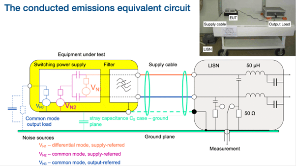
As illustrated in Figure 2, a typical switched-mode power supply generates both differential and common-mode noise.
The common-mode noise couples through parasitic capacitances between the device under test (DUT) and the test ground plane.
Importantly, this parasitic capacitance depends strongly on:
- PCB size
- Enclosure geometry (if the enclosure is metal)
- Distance from the ground plane
- Common mode output load (see Figure 2 illustration)
Reducing the common-mode output load height from 80 cm to 10 cm increases the parasitic capacitance by approximately eight times. From basic capacitance relationships, this leads to a significant increase in displacement current (C·dv/dt).
This effect is further exacerbated by modern high-speed switching technologies, such as GaN devices, which exhibit very high dv/dt and have a relatively high switching frequency.
This phenomenon predominantly affects the 150 kHz to ~5 MHz frequency range, as shown in Figure 1.
While noise from switched-mode power supplies in this frequency range is often assumed to be differential-mode, the cases discussed here represent low-frequency common-mode noise [1], driven by strong capacitive coupling to the ground plane.
Using a LISN mate or current probe [2], the common-mode nature of the noise was confirmed experimentally.
A common first attempt at mitigation is adding ferrite cores to the cable. In this case, multiple turns using ferrite material 75 were tested — but with little improvement.
The reason is simple: insufficient impedance at low frequencies (typically, the impedance a multi-turn ferrite core can provide is below 500 ohms).
How about adding a filter? To demonstrate this, we connected an off-the-shelf mains filter to the input mains lead, and later close to the battery, and this did not improve the results (note that the charger has a good filter design already).
The filter has limited common mode rejection because the Y caps has nowhere to “ground” in this case.
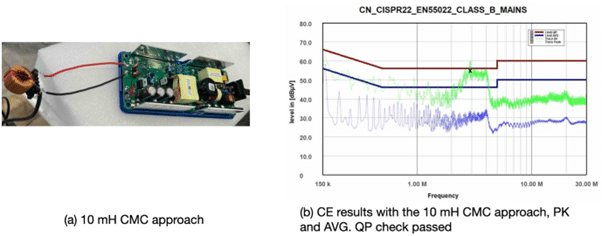
The final effective solution involved adding a 10 mH common-mode choke (CMC).
At 1 MHz, this provides approximately 62.8 kΩ of impedance, far beyond what a ferrite core can realistically achieve in this frequency range.
Case Study 2: When “Grounding” Makes Things Worse
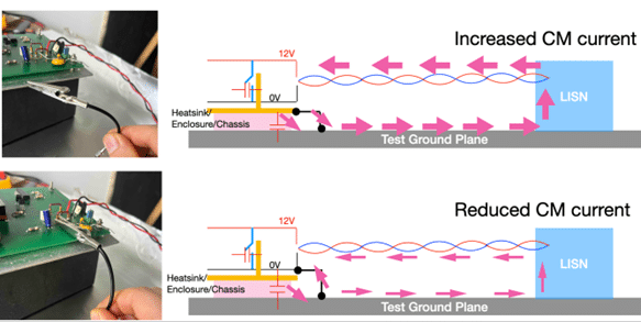
The second case study involves a product (automotive/defense application) where the PCB 0 V reference cannot be directly connected to the metallic enclosure due to functional and safety constraints.
During troubleshooting, engineers observed that connecting the metallic enclosure to the test ground plane actually increased conducted emissions, particularly at lower frequencies.
This seemed counterintuitive — after all, grounding is commonly assumed to reduce noise.
Noisy ICs or switching devices on the PCB inject noise into the enclosure via capacitive coupling.
Effective grounding requires that noise currents have a low-impedance return path back to the source. It is important to understand that the noise source is on the PCB.
In this case, grounding the enclosure alone provided a direct conduction path to the test ground plane, but not back to the PCB, since PCB 0 V was floating.
This worsened common-mode noise at lower frequencies. At higher frequencies, the impedance of the parasitic capacitance decreases, reducing the impact of this direct connection.
To demonstrate this, we set up a simple test arrangement and illustrate the common-mode current paths for two different configurations, as shown in Figure 4.
Readers who wish to see how the current is measured and how the underlying assumption is demonstrated are encouraged to watch a short online video [3].
The preferred solution is to connect PCB 0 V to the enclosure using safety-rated capacitors. Larger capacitance values improve low-frequency EMC performance, but designers must consider leakage current limits.
If capacitance is constrained, two alternative strategies can be considered:
- Place an electrostatic shield between the noisy circuitry and the enclosure, and connect it to PCB 0 V.
- If disconnecting the enclosure from the test ground plane is not possible, introduce a low-frequency ferrite core on the ground wire to limit injected common-mode current.
Conclusion
This article highlights the importance of understanding common-mode current paths in conducted emissions testing.
Parasitic capacitances — often introduced unintentionally through test setup and grounding configurations — can dominate results and lead to confusing failures.
Once engineers can clearly visualize the noise coupling mechanism and return path, effective and targeted solutions become much easier to implement.
Ultimately, seeing the noise path is the first step toward controlling it.
References
[1] Min Zhang, Signal Integrity Journal, Troubleshooting Low-Frequency Common Mode Emissions, https://www.signalintegrityjournal.com/articles/2965-troubleshooting-low-frequency-common-mode-emissions
[2] Ken Wyatt, Workbench Troubleshooting EMC Emissions (Volume 2): Simple Techniques for Radiated and Conducted Emissions Troubleshooting and Pre-Compliance Testing
[3] Youtube link, Demystifying Grounding in EMC Episode 1, https://youtu.be/i2HDL1mEAMg?si=YHkQ2C0x04vcX94n