Measurement uncertainty is not limited to EMC.
Robert D. Goldblum, Publisher Emeritus, ITEM Media
ANSI C63.23/D11, is a draft standard for Electromagnetic Compatibility – Calculations (Computations) and Treatment of Measurement of Uncertainty being prepared by the American National Standards Institute (ANSI).1 When published, this standard is likely to be adopted by the Federal Communications Commission (FCC), the European Union (EU), and other international regulatory bodies throughout the world where their specification limits are considered to be absolute and not subject to tailoring. The International Standards Organization (ISO) Guide to the Expression of Uncertainty in Measurement [usually referred to simply as GUM], set out the initial worldwide requirement for dealing with uncertainty.2 Published in 1993, it requires that a statement of uncertainly accompany every measurement. Consequently, all commercial equipment requiring FCC or EU approval will be subject to these requirements sometime in the future. All reports will talk about the probability of meeting the standard’s required limits rather than using just a pass/failure statement. The GUM has found wide acceptance in the United States and other countries and has been adopted by various regional metrology and related organizations including NAVLAP, A3LA, EUROLAB, EU, EA, EUROMET, and others.
It is not currently proposed that measurement uncertainty requirements be applied for MIL-STD-461, since the limits have been derived in a manner that subjective deviations and tailoring are often applied. Also, there is no indication that the military is considering uncertainty in any of its EMC and related tests at this time. Uncertainty is most important when the risk of deviation from a certainty is critical. Older military EMI system compatibility standards, such as MIL-E- 6051 required a 6-dB safety margin for susceptibility testing and a 20-dB safety margin relative to electro-explosive device [EED] susceptibility testing. These margins usually accounted for the uncertainty in the measurements, whether or not that was the original intent. Such may not be the case today in regard to MIL-STD-461 or MIL-STD-464.
The subject of uncertainty is not limited solely to EMC measurements. It applies to all measurements, such as the measurement of frequency, amplitudes, stability, field intensity, and just about any other type of measurement. ANSI C63.23 addresses only EMC emission measurements at this time. Uncertainties of immunity measurements are still being studied for further consideration.
In metrology, measurement uncertainty describes an observed value of a physical quantity. That observed value likely encompasses the true value.3 Assessing and reporting measurement uncertainty is fundamental in engineering as well as in experimental sciences such as physics. The concept of measurement uncertainty takes into account both systematic and random error of measurement and depends upon both the accuracy and precision of the measurement instrument. The lower the accuracy and precision of measurement instrument are, the larger the measurement the uncertainty will be. It is important to note that both precision and measurement uncertainty are often determined as the standard deviation of the repeated measures of given value. This definition, however, is correct only when the instrument is accurate. When it is inaccurate, the uncertainly will be larger than the standard deviation of the repeated measures.
When a measurement is taken under constant conditions, random affects such a noise on DC voltage, will affect the measured value. Systematic errors arise when a given quantity, which remains unchanged as a measurement is repeated under constant conditions, influences the result—e.g., calibration errors. If the expected error is constant and known, it may be possible to reduce such effects by applying a correction factor to the data. If this corrective step is not taken, the full error must be included in an uncertainty budget.
To keep uncertainties reliable, the GUM proposes to multiply uncertainties by a correction, factor kp = 2. NIST states in its Technical Note 12974 that kp is more likely to be equal to 2.3 for a 95 percent reliability; but the value k = 2.0 is used in ANSI C63.23/D11
An uncertainty budget lists the likely error sources and estimates individually their limits of uncertainty and probability distribution. To establish this list, a reasonable degree of familiarity with the test method and instrumentation is needed. When creating the list, it is better to be inclusive rather than overly selective. For example, if a particular contribution turns out to be negligible, it is still better to acknowledge its presence. Once each component has been analyzed, the individual components are summed to produce the final result for the measurement. In the analysis, sources of uncertainty can be grouped into one of two categories based on their method of evaluation:
- TYPE A: random effects
- TYPE B: systematic effects.
TYPE A evaluations are done by calculations from a series of repeated observations using statistical methods and results in a probability distribution that is assumed to be normal. For any measurement, the type A evaluation should be made using that procedure and configuration that is typically involved in the test typically using a standardized EUT (equipment under test). This method gives a measure of likely contribution caused by random fluctuations such as the uncontrolled variation in antenna position, losses caused by cable re-connection, different test personnel, etc. Since most test labs test different EUTs, not the some one over and over again, a Type A analysis is not appropriate since it does not take into account variations arising from the EUTs.
When only one measurement is made on the EUT, and the result is close to the limit, it is advisable to perform several measurements on the EUT itself, at least at those frequencies that are critical. The uncertainly is reduced (proportional to the square root of the number of measurements as shown in Equation 1.
S(Q) is the is the standard deviation of a series of n such measurements (qk). Also, s(qk) is the standard deviation of a series of n such measurements qk. Note that taking four repeated measurements on the EUT and then taking the mean value will determine the uncertainty caused by random effects. This has no bearing on other contributions of testing different EUTs. For that determination, type B analysis is required.
Type B evaluations are done using calibration certificate data that includes uncertainty, previous measurements, manufacturer’s specifications, and an understanding of instrument behavior. They are used for systematic effects—i.e., those that remain constant during the measurement but may change when the measurement conditions, method, test personnel, or equipment are altered Equipment calibration, mismatch errors, and errors arising from constant deviation in the physical set-up are typical examples of problems encountered. Other contributions must be calculated from knowledge of the nature of the test. For instance, deviations in field strength caused by errors in antenna separation are normally assumed to follow the 1/r law, but this assumption may not always hold true. Still, it must be assumed to accurate because simplifications are necessary to keep uncertainty calculations practical.
Type B contributions need another step before they can be summed. This involves the determination of the appropriate probability distribution for each contribution. For EMC test, these are:
- NORMAL – calibration uncertainties with a statement of confidence
- RECTANGULAR – manufacturer’s specifications
- U-SHAPED – applicable to mismatch uncertainty where the true value is close to the measured value is low
- TRIANGULAR – assigned when the majority of the values between the limits lie around the central point.
Once each contribution has been converted (as detailed above) to a standard uncertainly, the combined uncertainty, uc(y), is obtained for m contributions by taking the square root of the sum of the squares of the individual standard uncertainties.
The expanded uncertainty is obtained by multiplying the combined uncertainty by a correction factor of k = 2 for a level of confidence of 95%. This is usual practice for industrial and commercial measurement applications.
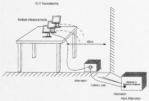
Figure 1 is an illustration of a conducted emission configuration with uncertainty drivers. 1

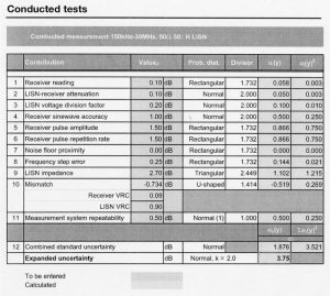
Every element of the measurement configuration has a tolerance, [a plus and minus value]. For instance, the antenna factor can have a tolerance of ± 2 dB, test site imperfections of ± 4 dB, receiver pulse amplitude accuracy of ±1.5 dB, and so forth. Table 1 4 shows a very wide radiated emission test uncertainty budget over the frequency range of 30 MHz to 1 GHz.

In this example, many accuracy tolerances, or contributions to the error budget, are overestimated because some of them apply only to a small part of the overall frequency range of 150 kHz to 30 MHz. It should be noted that every time an element is added to the test configuration (e.g., an attenuator) an additional contribution must be added to the error budget. A different person running the same test can contribute another tolerance value as can repeatability of the EUT. For simpler test configurations, lower error budgets are obtainable. (Note: A similar table can be derived for radiated emissions.)
The tolerance value for each element used in the test configuration is listed in the Value column of Table 1. The relevant probable distribution of each contributor is then taken into consideration (normal. rectangular, U-shaped) and triangular] using a devisor defined for each. The values shown in the last column of Table 1 (U[y]) are then added per Equation 2. Then, a constant factor of k=2 indicating a 95% confidence of assumptions is used to multiply the result, which shows a combined standard uncertainty of 1.876 dB, and an expanded uncertainty of 3.75 dB. (See references for additional detail.)
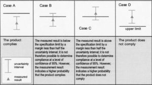
Table 2 2 shows the impact of an uncertainty of 3.75 dB relative to compliance to a conducted specification limit. The horizontal line represents the limit level. The vertical line shows the uncertainty interval calculated in Table 1 (3.75 dB).

The subject of measurement uncertainty and the way it is to be applied for CISPR-based emission standards have been set out in a new part of CISPR 16-4 (3).5 The thrust of this document is that measurement uncertainty must be calculated and must be quoted in the test report, including a detailed description of how it has been derived. If the calculated uncertainty, Ulab , is less than that given in Table 32for UCISPR ,
- Compliance is deemed to occur if no measured value exceeds the limit;
- Non-compliance is deemed if any measured value exceeds the limit.
If the calculated uncertainty is greater than UCISPR, then
- Compliance is assumed if no measured value increased by [Ulab – Ucispr], exceeds the limit;
- Non-compliance is assumed if any measured value increased by [Ulab – UCISPR], exceeds the limit.

Note that ‘Disturbance power’ is unique to CISPR and is not applicable in MIL-STD-461. CISPR generally accepted values [UCISPR] apply to measurement instruments only.
A hierarchical relationship is achieved by calibrating equipment through the use of standards of better accuracy.6 It could be illustrated as follows:
National Standard……………………………..Accurate to 0.02%
Calibration Laboratory…………………………………………..0.13%
Production Equipment…………………………………………..0.6%
Manufactured Product……………………………………………8%
In summary, it must be noted that measurement uncertainty is the way of the future and understanding what is involved and what it means is important to both the engineering community in general and EMC community in particular. Whether or not it will eventually be applied to military test requirements remains to be seen. Measurement uncertainty is not limited to EMC. It will also apply to ALL measurements and could certainly change the world’s systems of metrology. It is recommended that the reference material be read for a full understanding of the subject.
REFERENCES:
1 Workshop. Draft ANSI C63.23/D11 EMC Measurement Uncertainty Workshop. The Institute of Electrical and Electronic Engineers, Inc., Detroit, Michigan. August 2008.
2 Guide to the Expression of Uncertainty in Measurement. ISO/IEC/OIML/BIPM . Prepared by ISO/TAG 4/WG 3: January 1993.
3 EMC Measurement Uncertainty – a Handy Guide. Schaffner EMC Systems, Ltd (now Teseq Inc.).52 Mayfield Ave. Edison, NJ 08837
4 NIST Technical Note 1297. Guidelines for Evaluating and Expressing the Uncertainty of NIST Measurement Results.1994 edition.
5 Technical Report ,CISPR 16-4-3 TR 2004, Specification for radio disturbance and immunity measuring apparatus and methods – Part 4: Uncertainties, statistics and limit modeling – Statistical considerations in determination of EMC compliance of mass-produced products.
6 Hutchins, Mike. Calibration Certificates: Look Closer Before Filing. Agilent Technologies UK Ltd (now Teseq, Inc.)
ABOUT THE AUTHOR
Robert D. Goldblum is Publisher Emeritus of ITEM Publications. Bob is a Fellow of the IEEE and a member of the IEEE EMC Society Board of Directors.


