Introduction
Medical devices must be designed with proper isolation of patients from earth. For that reason all medical products have floating circuits. This means that the circuit ground is isolated from the earth ground. ESD protection in floating circuits with isolated grounds can be very challenging. Sometimes conventional ESD protection methods may not work. It is important to understand how ESD is created and how it is discharged. The discharge of the ESD will always depend on the circuit characteristics. In this blog I will describe my recent ESD troubleshooting experience and what I have learned from it.
Background
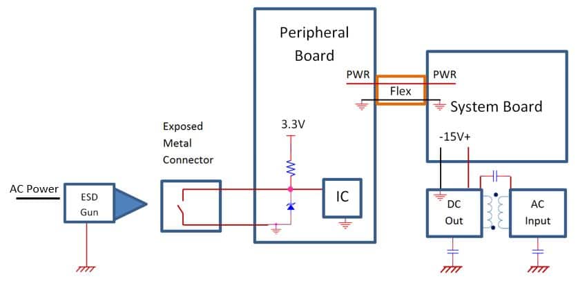
Recently I worked on a medical product with a peripheral support board that was connected to the system board via a 4-inch long flex cable. The ground connection, power lines and signals came to the peripheral board through one flex cable. The peripheral board had three peripherals that it supported. Each peripheral communicated through a UART to a Quad UART to USB converter IC which communicated with the system processor. One of the peripherals had an exposed metal coupler for a patient-coupled pressure hose. This coupler had a mechanical switch that closed when a hose was inserted. The switch was not isolated from the connector metal body. The switch had two 3-inch long wires that connected to the peripheral board. Figure 1 depicts the high level diagram for this one peripheral.
ESD Test Observation
The metal connector is exposed and easily accessible to human touch. Thus the IEC 61000-4-2 ESD test methods applied. Per the edition 4 of the IEC 60601-1-2:2014 the medical equipment must meet level 4 ESD discharge (8kV contact and 15kV air). The connector was tested at 15kV air discharge. With the switch inside the connector closed. After the first discharge all three peripherals went offline and became latched in an unknown state. They required a hard power cycle to operate again. After several discharges the IC pin for the connector switch detection was damaged and caused the IC to malfunction requiring a replacement.
ESD Troubleshooting
ESD in a Floating Circuit
The phenomenon described above was also seen at 4kV air discharge. At first this was strange because there was a TVS diode placed at the switch detection pin of the IC. However, the TVS diode was not helping. It was not useful at all because the ESD energy was coupling onto the board as common mode. Figure 2 shows the LTSpice ESD RF circuit model of the diagram shown in Figure 1. The trace inductance and the ground inductance for points shown in the schematic were measured at 1MHz and 100kHz using an LCR meter.

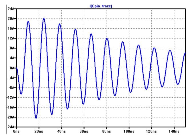
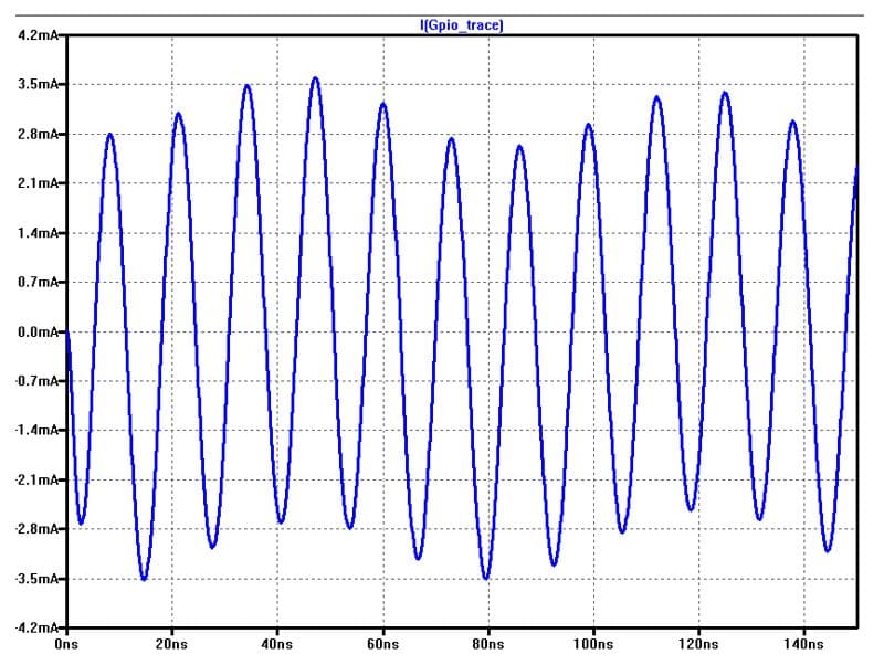
From Figure 2 it is understood that the ESD gun is referenced to earth ground so the discharge current wants to go back to earth. The only way the current finds its way to earth is to follow the path that leads to earth. Since the DC side of the AC/DC supply is connected to earth through a 220pF Y-Cap the ESD current will want to travel through the peripheral board, the flex and the system board as common mode. However, because the peripheral board is grounded only through the flex cable there is a lot of inductance in the ground connection. Because of this inductance a tank circuit forms and oscillates until all of the energy is dissipated across the IC and other components. Figure 3 shows the simulated oscillation at the input to the IC.
Please note that because the peripheral board is floating, none of the conventional ESD protection methods work. The ESD energy reference is not the same as the floating ground reference used by ESD protection devices.
Solution
In a situation like this there are several options that can be good solutions. Options listed in this article have been tested and were proven to be effective.
Isolate the Input
The most effective solution is to isolate the point of discharge from the rest of the circuit. The following techniques could be used to isolate the discharge point from the circuit:
- Optical isolators
- Requires splitting of grounds and a power source
- Requires space with a minimum area of 1cm square
- Current limiting resistors
- If shorter than 0.5 inch the ESD will arch across; it must be isolated on each side
- Both the ground and the signal must have resistors
- Mechanical isolation of the switch
- Requires a design change and retooling
- Off-the-shelf components may be difficult to change
- Design change timeframe may not meet the product release deadline
Isolation option was simulated by placing large resistors in series with the switch wires. Figure 4 shows the schematic.

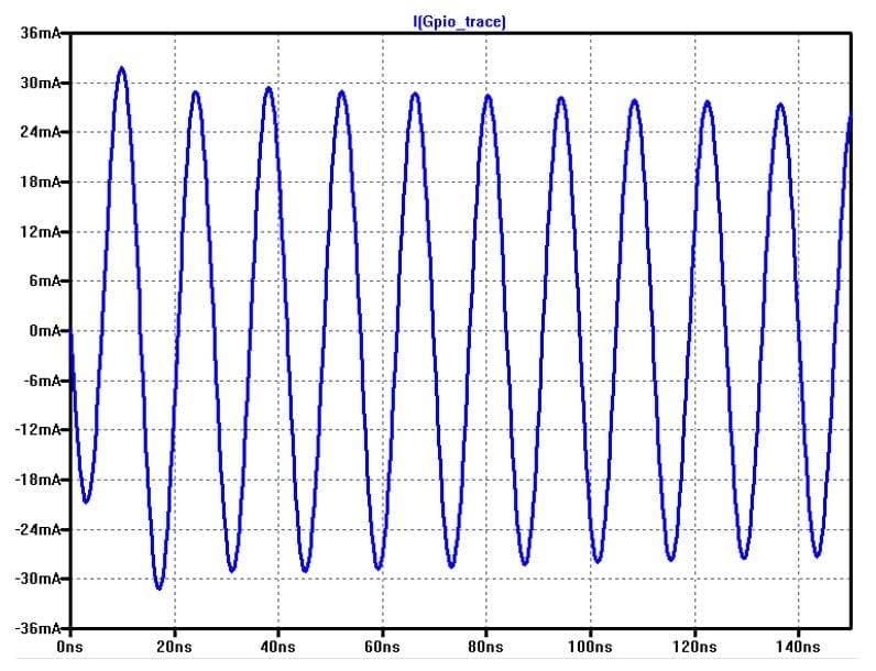
Placing 10k resistors in series with the switch wires reduces the ESD current to about 60mA peak-to-peak range as shown in Figure 5. The client preferred this solution and we tested it at 15kV air discharge over 600 times and had no observations. Similarly other types of isolation methods worked just as well.
Bypass the IC
Another solution is to bypass the IC by redirecting the ESD charge as shown in Figure 6.
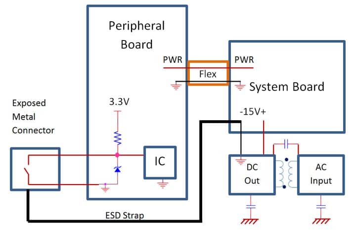
Since the ESD energy wants to go to the system ground, providing a low impedance and low inductance ESD strap from the metal connector to the system ground allows all of the ESD current to be shunted into the system ground. This way the susceptible IC is not affected. Note that the system ground is still an isolated ground, but because it is a much larger board it has more capacitance to earth ground and has a Y-Cap connection to earth ground. That’s the reason the ESD current wants to go to the system ground. Figure 7 shows the circuit model for the ESD strap connection.

The ESD strap will redirect almost all of the ESD current into the system ground which is has more capacitance to earth. Figure 8 shows the current at the IC input, which becomes insignificant.
Preventative Design
The ideal way to provide ESD prevention for floating circuits is to make sure that there is solid isolated grounding across all boards. In the case described above, the peripheral board should have been provided additional low impedance connection to the isolated system ground via grounding screws or grounding straps.


