Before deploying microwave and millimeter-wave devices and systems within 5G, the Internet of Things (IoT), and high-speed wireless communication, it is essential to predict their performance. This need has increased the demand for virtual test platforms through simulation software.
High carrier and system bus frequencies are necessary for high-data-rate communication between multiple devices present in such systems. However, increased operational frequencies may induce undesirable and troublesome electromagnetic compatibility (EMC) and electromagnetic interference (EMI) issues, especially when communication is congested. Moreover, the impact from other physics is no longer negligible in mmWave devices. Multiphysics phenomena, such as structural deformation caused by heat expansion, need to be a part of the design consideration as well. Fortunately, a wide range of EMC and EMI scenarios can be virtually emulated and tested without having to elaborately adapt test configurations to real-world environments.
Using electromagnetics simulation software for evaluating device functionality reduces time and costs during the development and production cycle. Virtual evaluations can be performed prior to fabrication, test, and manufacture, and are an important component in reliable quality control processes.
The goal of simulation is to describe the real world as closely as possible on the computer by using proven physics equations. Ideally, the numerical model is used to mimic multiple physical phenomena representing a great variety of operational conditions, which is hard to realize in a lab environment. Accurately analyzing real-world designs and conditions comes at a cost. The more complex the analysis, the more computational resources are needed. Therefore, engineering judgment is used for excluding unnecessary parts from the analysis and for configuring the simulation settings to ensure efficient computations.
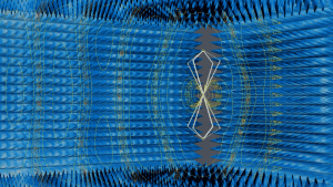
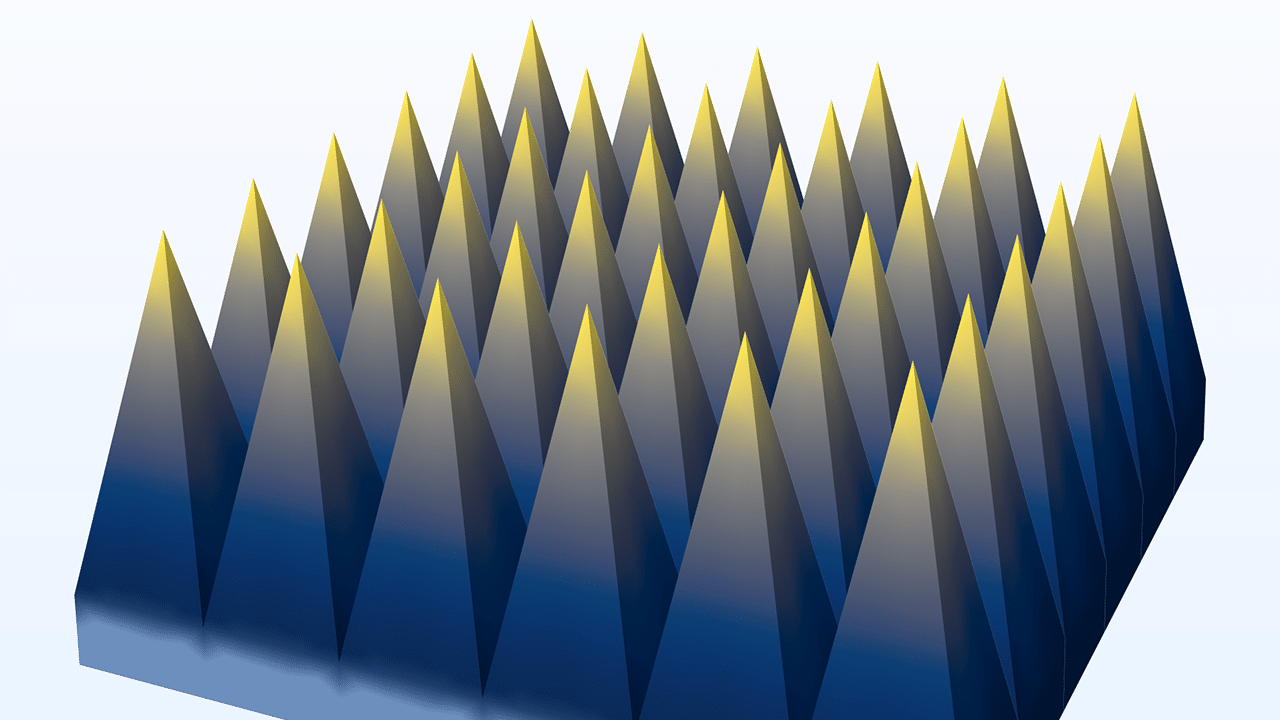
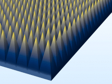
When evaluating EMI and EMC performance of radiating devices, test engineers often perform measurements in a fully anechoic chamber. Simulation tools are used to set up a numerical environment that can reproduce such tests virtually (Figure 1) by using, for example, the finite element method (FEM). For instance, the pyramidal absorbers that are attached to the anechoic chamber walls contain lossy conductive carbon particles. The absorbers attenuate the incident electromagnetic waves gradually with only small amounts of unwanted reflections. For efficiency, instead of modeling the full-sized wall of absorbers, the simulation uses only a single pyramidal unit cell with periodic boundary conditions (Figure 2). This is an efficient way of estimating the performance of the complete set of absorbers to make sure the reflectivity is at a minimum. Even if the model consists of just a single unit cell, the periodic boundary conditions make it equivalent to an infinite array of pyramidal absorbers. The effective homogeneous material properties obtained from the unit cell simulation are then used for the entire anechoic chamber wall.
To validate the virtual version of the anechoic chamber, a wideband biconical antenna is placed inside the anechoic chamber. The performance of the antenna (for example, far-field radiation patterns and S-parameters) is computed to validate that there is no degradation of performance due to the incomplete absorber characterization.
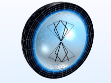
Although the real-world representation of the antenna inside the fully anechoic chamber in the simulation is visually quite appealing, as shown in Figure 1, its computational cost is unnecessarily high. The simulation can be made much faster and more efficient in terms of memory usage by using a numerical technique that is equivalent to the anechoic chamber walls. Such techniques involve using a perfectly matched layer (PML) and absorbing boundary condition features. To efficiently study the near and far fields and other antenna parameters, it is sufficient to place the same biconical antenna in a much smaller surrounding air domain enclosed by a perfectly matched layer (Figure 3).
In order to simulate a large system efficiently, it is crucial to choose proper numerical boundary conditions. In addition, eliminating design details that are deemed to have a negligible impact on the results, just keeping the relevant components, can make further efficiency gains. By using PMLs, a large system can be simulated and not limited to just device-level modeling.

In Figure 4, the electric field transmitted from a fictitious radiating device on the rear windshield of a car is studied to see the radiated emission effect over the cable harness inside. The PML covers the upper half-space, absorbs all outgoing waves, and ensures that reflected waves do not bounce back onto the car. Meanwhile, the bottom ground and the car body generate reflection and multipath fading effects on the cable harness. The electromagnetic waves coupled to the cable are a source for unwanted conducted emission as well. In a real car system, it would be hard to access and relocate the source and victims for the EMI/EMC test. However, by using simulation, it is possible to analyze arbitrary configurations. In this way, by not being limited by physical testing, engineers can produce more robust system designs.
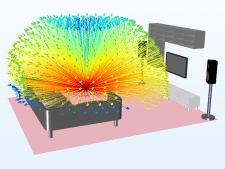
By using simulation, one can estimate the actual performance of devices for IoT applications when they are deployed in a real environment. IoT devices may be placed in a living room, a garage, or other spaces in a house. The electrical size of the problem in terms of the number of spanned wavelengths can easily exceed what can be addressed by so-called full-wave numerical methods. Full-wave methods include the finite element method (FEM), the finite difference time domain (FDTD) method, and the method of moments (MoM). There are alternative computational electromagnetics approaches available for approximating the performance of IoT devices without sacrificing too much accuracy. In addition, such approximate methods can produce useful results while still using limited computational resources. One such approach is the method of ray tracing. Figure 5 shows multiscale simulation capabilities when ray tracing is employed together with FEM. The part of the simulation that uses FEM analyzes a small simulation domain surrounding the antenna of a wireless router that includes a truncated surrounding air domain. Rays are launched from the antenna location, and their initial strength is proportional to the directional intensity of the 3D far-field radiation pattern of the antenna. The antenna coverage inside a media room (Figure 5) can be approximated quickly without long simulation times or excessive memory usage. This multiscale electromagnetics modeling technique is a great alternative for overcoming the limitations of traditional computation methods for large EMI and EMC problems.
Simply combining existing computational methods can overcome the limitations of traditional numerical analysis. Two such situations are when you need to produce wideband results with high-frequency resolution or when you need to analyze signal integrity and time-domain reflectometry (TDR) for a large device. Such simulations can be very time consuming. However, in both cases, the computational performance can be greatly boosted by conducting a fast Fourier transform (FFT), either from the time domain to the frequency domain or the other way around. For example, you can first perform a transient analysis and then run a time-to-frequency FFT to achieve a wideband S-parameter and far-field calculation in the frequency domain. Alternatively, you can first perform a frequency sweep and then run a frequency-to-time FFT for a time-domain bandpass impulse response. This is useful for time-domain reflectometry analysis, such as identifying a defective part of a transmission line, which results in impedance mismatch and signal quality degradation.
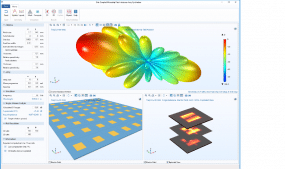
Simulation provides virtual analysis platforms for a wide range of test scenarios. However, learning how to use electromagnetics simulation software may not be the best use of time for everyone in an organization. Limited training and access to simulation software may restrict usage of electromagnetics simulation tools to a small set of expert users. Completed numerical EMI and EMC test models may frequently need new input parameters in order to adjust to a real-world test environment’s variations. The need for updating boundary conditions, mesh, and postprocessing settings outside of the simulation group can cause unexpected delays in the development cycle. The good news is that simulation software has evolved to accommodate specialists who are not dedicated simulation engineers. The simulation models can be converted to easy-to-use apps (Figure 6). An app has a straightforward, specialized user interface (UI) and can be shared with colleagues and customers through existing web browsers or as a standalone executable file. Such standalone apps do not require purchasing extra software licenses and can run regardless of the operating system. A large number of people involved in EMI test projects can easily access the virtual test kit provided by an app and optimize the product without learning how to use the software behind the curtain.
The variety of simulation tools that support multiple numerical methods within electromagnetics helps engineers and researchers not only to design conventional devices, such as filters, couplers, antennas, and waveguide structures, but also to test EMI and EMC problems in applications for 5G, IoT, and wireless communication. Conventional electromagnetics analyses can be extended to include multiple physical effects using multiphysics simulation. The simulation software industry is also evolving to meet the demands of the fast-paced market for emerging high-speed communication technologies and help more people benefit from simulation.
