Have you ever had a signal integrity issue that did not have its toll on EMC? If you did then you should consider yourself lucky to have avoided this nightmare.
I. Situation:
An I2S bus master clock driver is set to 12.288MHz and run at 3.3V. Drive strength is at 50-Ohms. Rise time is at 2ns. Fall time is at 2ns.
The driver is located on the “master board” and the bus lines travel through a 4-inch trace to a board connector. From this connector signals are routed to another “slave board” through a 4-inch flex cable. On this “slave board” the bus lines travel for another 6.5 inches until they reach their destination, the receiver.
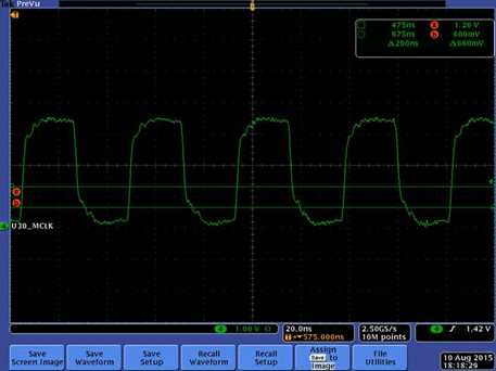
Amazingly the signal integrity of this layout looks acceptable as shown in Figure 1.

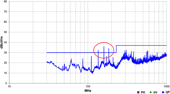
However, hiding behind this promising picture is EMC performance. Figure 2 shows the Radiated Emissions (RE) of this clock.

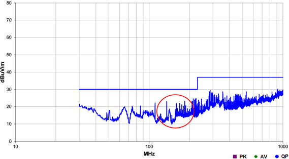
Three spikes shown in Figure 2 are at 135MHz, 160MHz, and 184MHz. In other words, the 11th, 13th, and 15th harmonic of the master clock radiating through the flex cable were causing emissions failures. To address this issue, the EMC design engineer had placed a T-Filter (Murata NFL18ST506H1A3D) at the input of the flex cable connector on the “Master Board”. This filter has a cut-of frequency of 50MHz. As shown in Figure 3, the implementation of the filter had a dramatic effect on RE.

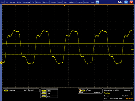
Figure 3 is quite good to look at. Having a 5dB margin is a luxury in the EMC world. However, the joy of a 5dB margin did not last long. When the master clock line was re-analyzed for Signal Integrity (SI), well, Figure 4 was the result.

Adding the T-Filter to the transmission line added 110pF of capacitance to ground resulting in a reflection caused by a phase shift. Due to this reflection the VOL margin was lost and introduced a concern of false edge detection.
II. Solutions considered without the use of filters:
Note: The design team rejected all proposals for layout changes because of procedural and requirement constraints. Other solutions needed to be considered.
Reducing the drive strength
Increasing the rise and fall times can mask reflections, but not always. This solution would work if the transmission line was not 14 inches long. Reducing the drive strength worked great for EMC, but resulted in an underdriven transmission line.
Reducing the line voltage
The master clock was run at 3.3V, however the I2S bus can operate at 1.8V without any issues. Luckily there was a place holder for a level shifter (SN74AUP1T34) implemented on the PCB whose pads were populated with zero-ohm resistors. Implementing the level-shifter to drop the line voltage from 3.3V to 1.8V resulted in SI similar to Figure 1 and RE performance similar to Figure 3.
III. Avoiding this type of a problem:
Shorten the Transmission Line
The distance traveled by the transmission line between the I2S driver and the receiver should be as short as possible. Ideal situation for a bus traveling from the “master board” to the “slave board” is to place the driver and the receiver close to the connectors leaving/entering boards. In the example discussed if the trace length on the “slave board” was very short then placing the T-Filter may not have caused the signal integrity problem.
Properly Match Impedances
If the length of the transmission line is constricted due to some design constraints then it is important to make sure there is no mismatch at the source and load of the transmission line. One could consider a series match or a parallel match schemes (refer to Chapter 4 of Introduction to Electromagnetic Compatibility, 2006 by Clayton R. Paul).
Avoid Vias
We have seen cases where transmission lines cross board layers though vias. When cross-sectional dimensions of the transmission line change, the characteristic impedance of the line will change and will create a reflection at that discontinuity. A signal passing through a via will encounter a discontinuity.
SI Budgeting
It is important to determine the signal integrity budget of the transmission line. This can be done at the layout stage of the design. Using the Cadence/Allegro/Spice tools the margin/bandwidth-for-error can be calculated by adding capacitance, inductance and DCR to the transmission line. For instance, doing this will let you know how much added capacitance (due to filters, between traces, between connectors, etc.) you could tolerate on the transmission line and still have good SI.
IV. Summary
The layout of the transmission lines must be properly implemented following good design practices for SI. Having good signal integrity provides margin/bandwidth for implementing EMC fixes (if there is any), such as placing a T-Filter (or any other means of filtering) without distorting the signal significantly. Finally, it is always a good idea to have an EMC engineer review your board layout before building the board.


