Commercial EMC tests cover a wide range of products. These include the obvious ones like computers and their peripherals, but also cover household appliances, electric tools and a wide variety of other products. While the standards, including limits and test methods may differ, all EMC test standards have a few things in common. The most basic are the limits for emissions and the types and levels of immunity testing.
Emissions tests (and their associated limits) are put in place for commercial equipment primarily to protect radio and television broadcasting services. Other radio communications services are also protected. While a very few commercial emissions standards existed prior to the introduction of the personal computer to the marketplace, the proliferation of these devices spurred the development of standards and regulations around the world due to the large number of interference complaints directly traceable to these new devices. Early personal computing devices were designed and built with no regard to controlling radio frequency emissions and, as a result, they generated large amounts of RF emissions. Indeed, it could be argued that the early personal computing devices were broadband radio transmitters masquerading as computers. Mainframe computers had similar weaknesses, but as they typically weren’t installed in residential areas the impact was smaller.
Emissions testing typically comprises of two parts. Conducted emissions on power and telecommunications ports and radiated emissions. The breakpoint between the two (conducted and radiated) in commercial standards is 30 MHz. This frequency was chosen as at the typical test distances involved (3 meters and 10 meters today) frequencies above 30 MHz tend to provide plane wave (far field) emissions, allowing for fairly repeatable measurements from laboratory to laboratory. Below 30 MHz this may not be the case. Thus, conducted emissions are measured. Limits for powerline conducted emissions were set based on the source and victim devices being connected to the same circuit. Limits for conducted emissions on telecommunication ports are set assuming a certain conversion of the differential mode (desired) signals on the cable being converted to common mode (due to characteristics of the cable) which then radiates.
Conducted Emissions
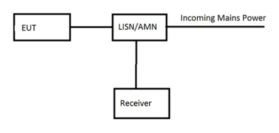
Conducted emissions on the incoming power lines are measured (typically) using a Line Impedance Stabilization Network (LISN) or Artificial Mains Network (AMN). These are two different names for the same box. The LISN or AMN is placed between the Equipment Under Test (EUT) and the incoming power line (mains) to provide a defined power line impedance and a coupling point to the receiver (Figure 1). The LISN or AMN is placed on the horizontal ground plane, or directly beneath it with the EUT connected directly to the EUT port. The block diagram below shows this test setup.Page Break

The EUT is placed either on the horizontal ground plane on the floor (with an insulating spacer) or on an 80 cm high non-conducting table, depending on the intended installation of the EUT (table top or ground mounted). The frequency range of interest is scanned with the appropriate detectors and bandwidth and the results are noted. Measurement are made on each conductor of the incoming line separately. Most commercial EMC standards have measurements made over the frequency range of 150 kHz to 30 MHz.
Radiated Emissions
Radiated emissions may be measured in either an Open Area Test Site (OATS) or an RF Semi-Anechoic Chamber (SAC). The OATS is the “gold standard” test facility. It consists of a large open area free of objects which might reflect RF energy. It typically is equipped with a reflecting ground plane. The size of the clear area is defined in various standards as an elliptical area whose major axis is twice the measurement distance and whose minor axis is the square root of 3 times the measurement distance. Experience has shown over the decades that these dimensions are too small. Doubling them has been tried and even that has been shown to have its weaknesses, especially when the OATS is surrounded by a chain link fence for security. The picture below shows a 30 meter OATS built in 1989 for Tandem Computers Incorporated near Hollister, California. The clear area is at least twice the required dimensions for a 30 meter site and takes a considerable amount of land. This site is no longer in operation, but it illustrates the point. The building on the ground plane was constructed of RF transparent material and covered the turntable. All utilities were run underground, including the air conditioning ducts with the air conditioning units being installed outside the clear area. The site was never utilized at a measurement distance of 30 meters, so it was a superb 10 meter site.

A significant weakness of the OATS facility is that in addition to measuring the emissions from the EUT it is a great facility to measure all the local RF ambient signals from broadcast and communications services, as well. If these signals are strong enough they will totally mask the emissions from the EUT that you were trying to measure. As a result, for best operation an OATS must be located in a very remote area. And this is no guarantee that the ambient level will remain low. Apple Computer had a great OATS near Pescadero, California that had a very low ambient when it was built in the 1980s. Apple ultimately stopped using the facility when the local ambient signals grew to the point where operation was no longer possible and moved totally to 10 meter SACs near their development facilities.
Regardless of whether measurement are taken at an OATS or in a SAC, the block diagram of the test set-up remains the same. Emissions from the EUT are measured using an antenna for the appropriate frequency range, a pre-amplifier (if necessary) and a measuring receiver. Measurements are taken with the antenna in both the vertical and horizontal polarities. See the block diagram in Figure 3

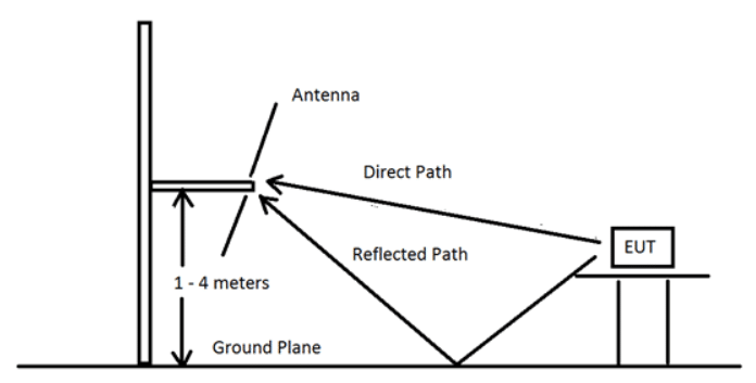
The need for height scans is shown by the diagram in Figure 4. The objective is to adjust the antenna height until the direct and reflected signals are maximized. An example of an antenna mast for this purpose is shown in the photograph above of the Tandem 30 meter OATS (Figure 2).

Emissions tests are required in many countries around the world. Immunity testing of commercial products is required in a smaller number of countries, but these are some major countries, so a manufacturer must be aware of them.
Commercial Immunity Tests
Commercial immunity testing typically covers the following types of tests:
- Electrostatic Discharge (ESD). There are two types of ESD tests – contact discharge and air discharge. In the contact discharge test the tip of the ESD simulator is placed on the test point of the EUT and the discharge is initiated. The discharge occurs inside the simulator and these tests are fairly repeatable. In the air discharge test the simulator is charged to the specified voltage and brought into contact with the EUT. The discharge, if it occurs, happens before contact is made jumping the air gap between the tip of the simulator and the EUT. How large this gap is depends of the atmospheric pressure, temperature, angle of approach, and relative humidity. It can also depend on how fast the operator approaches the EUT with the ESD gun Air discharge testing is not as repeatable, but it simulates a different ESD event. Both types of tests are typically required. For computer equipment CISPR 24 requires a contact discharge test at 4 kV and air discharge tests up to 8 kV. Tests are typically performed using the equipment and procedures called out in IEC 61000-4-2. The EUT is allowed to react to the test, but it must self-recover after the test. A classic example is a computer playing music over a speaker. You hear a POP! in the speaker when the ESD event occurs, but the music keeps playing afterwards. This is considered a pass. If the music stopped and required operator intervention to re-start, that would be considered a failure.
- Radiated electric field immunity. This tests the immunity of the EUT to nearby radio transmitters. The frequency range of 80 MHz to 1 GHz is typically tested, although newer standards have tests required as high as 6 GHz. This test is performed in a fully anechoic chamber or a SAC with removable absorbers placed on the floor. Signal levels are used that would annoy the neighbors and cause the local regulators to issue fines, so a shielded environment is a necessity. The current requirements in IEC 61000-4-3 (a commonly used basic standard) call for the E-field to be uniform to within certain requirements before the EUT is brought into the test volume. Four sides of the EUT are typically evaluated. The EUT typically must continue to operate through the test as though nothing was happening to it or must self-recover with no loss of data to be considered a pass.
- Electrical Fast Transients. This test introduces a series of rapid pulses into the EUT through the power and any signal lines that could exceed 3 meters in length. Like ESD testing, the EUT must operate after the test without operator intervention, but may react to the test as it occurs, so long as the system self-recovers with no loss of data. IEC 61000-4-4 calls out the test equipment and procedures for this test.
- Electric Surge. This test simulates what happens on the power input to the EUT when there is a nearby lightning strike. High energy surges are applied to the EUT line input. IEC 61000-4-5 details the test equipment and procedures for performing surge testing.
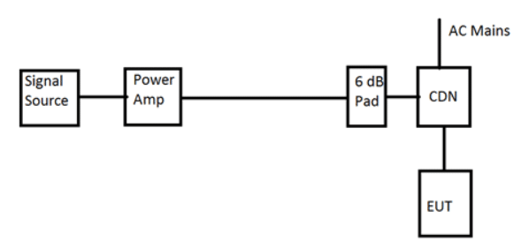
- Conducted RF. In commercial standards the breakpoint between conducted RF and radiated RF immunity testing is typically 80 MHz. Generating uniform fields much below 80 MHz is difficult. As a result, below that frequency RF energy is typically injected onto cables connected to the EUT. An example of a block diagram for such a test is shown in Figure 5. The 6 dB attenuator is placed as close to the Coupling Decoupling Network (CDN) as possible. While this isn’t clearly shown in IEC 61000-4-6, the reason for placing it as close to the CDN as possible is that it provides a matching impedance to the transmission line, maximizing power transfer to the CDN, whose input impedance is not precisely known. Otherwise, you may be throwing away half the power you paid to generate.

The typical frequency range for conducted RF immunity testing of commercial equipment is 150 kHz to 80 MHz.
- Power Frequency Magnetic Fields. This test is run for products which might reasonably be expected to have immunity problems with power frequency magnetic fields. Such products, as called out in CISPR 24 for example, might include Cathode Ray Tube (CRT) displays, magnetic field sensors and Hall devices. The EUT is placed in the middle of a large coil of wire through which a power frequency current flows. The current level to generate the specified field level (for example, 1 Amp/meter in CISPR 24) is run through the coil and the EUT is checked for proper operation. All three axes are tested. Most products do not require this test, but it is included in the product family standards. IEC 62000-4-8 details how to perform this test.
- Dips and dropouts. This test is designed to simulate real world examples of momentary input power voltage fluctuations. In the case of CISPR 24 (and CISPR 35) there are three tests that are performed, typically by a computerized power source. The first is a >95% voltage reduction for one half cycle of the incoming power. The voltage change occurs at the zero crossover point on the power waveform. This simply means that one half cycle of the incoming power to the EUT is chopped off. The EUT is allowed to react, but must self-recover without operator intervention. The second test is a 30% reduction (70% residual voltage) for one half second (25 cycles at 50 Hz or 30 cycles at 60 Hz) – a short brown-out. Again, the EUT may react, but must self-recover. The third commonly used test is a >95% reduction in input voltage for 5 seconds. It’s like the power cord was pulled out of the wall socket for 5 seconds and then plugged back in. Obviously, unless the EUT has a built in battery or UPS, it will crash. As long as function can be restored by the operator in accordance with the instructions and no data protected by battery back-up is lost or damaged, the EUT passes this test. IEC 61000-4-11 provides the details on how these tests are to be run.
The test levels utilized in commercial immunity tests are designed to provide a reasonable level of certainty that the product will operate in its intended environment. They do not represent the worst case that a product might experience in the field, but they have been shown over the years to be adequate. Indeed, most products exhibit higher levels of immunity that required when tested to their breaking point and the design features used to meet the emissions requirements typically are adequate for providing this level of immunity.


