Kenneth Wyatt
Wyatt Technical Services LLC
History of Spread Spectrum
Figure 1 – Actress, mathematician and inventor, Hedy Lamarr. Courtesy of http://www.hedylamarr.com
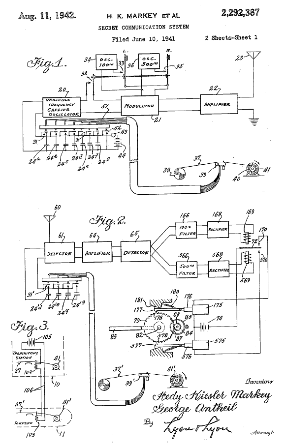
During WW2, the U.S. Navy was having problems with radio-controlled torpedoes that were being jammed by high-strength RF signals tuned to the same frequency as the transmitting radio. In August 11, 1942, Austrian actress, Hedy (Lamarr) Keisler Markey [Ref 1] and pianist and composer, George Antheil, with the help of an electrical engineering professor at the California Institute of Technology, solved this problem and were granted U.S. Patent Number 2,292,387 for a “Secret Communication System” [Ref 2] diagrammed in Figure 2. The device used a mechanism to rapidly switch between several frequencies on the transmitter (what is now called frequency hopping). A similar device on the receiver in the torpedo switched between the same frequencies and captured the transmitted signal. The signal controlling the torpedo never remained at any individual frequency long enough to be jammed by an external RF signal at a single frequency. The technology for this was based largely on the mechanism used for player pianos – a loop with coded holes. A special sync code was used to match up the initial hopping sequence.
Figure 2 – Original patent drawing for a “Secret Communication System”. Note the two coded roller strips that switch in a bank of several capacitors, which cause the transmitted and received frequency to hop in sync.
As Hedy (Lamarr) Markey and George Antheil explain in their patent application:
“This invention relates broadly to secret communication systems involving the lie of carrier waves of different frequencies and is especially useful in the remote control of dirigible craft, such as torpedoes. . Briefly, our system as adapted for radio control of a remote craft employs a pair of synchronous records, one at the transmitting station and one at the receiving station, which change the tuning of the transmitting and receiving apparatus from time to time . . . we contemplate employing records of the type used for many years in player pianos, and which consist of long rolls of paper having perforations variously positioned in a plurality of longitudinal rows along the records. In a conventional Player Piano record there may be 88 rows of perforations. And in our system such a record would permit the use of 88 different carrier frequencies, from one to another of which both the transmitting and receiving station would be changed at intervals. . .”
While their prototype system used up to 50 perforations, or frequency hopping codes, it still formed the basis of the frequency hopping spread spectrum systems used today. Unfortunately, the U.S. NAVY never ended up using that system during WW2. However, once the patent lapsed, they did start using it during the Cuban missile crisis. Unfortunately, Lamarr was never credited until years later.
A more sophisticated version of this technique was used later to reduce jamming vulnerability in military communication systems and ultimately another jump in development was the use of direct sequence spread spectrum, which is used in today’s cellular and cordless phones.
Spread Spectrum Clock Generation for ITE Products
Spread spectrum clock generation (SSCG) or “dithering” (modulating the clock frequency), has been around for a long while, even before the PC and printer manufacturers got on the bandwagon. There are also several ways to produce a dithered clock, using discrete logic or FPGAs.
In August 1994, Keith Hardin, John Fessler and Donald Bush, engineers from Lexmark International, Inc. (a spin-off from IBM), introduced the concept at the IEEE International Symposium on EMC that year. It was based on a chirp spread spectrum (CSS) method, where a square wave clock signal is modulated with a low-frequency signal to produce a series of fixed-frequency, lower-amplitude, harmonics. Their paper, “Spread Spectrum Clock Generation for the Reduction of Radiated Emissions”, was also voted a runner up for “best paper” [Ref 3]. They built the SSCG into a prototype printer and demonstrated it during that symposium. It created quite a stir among the attendees.
Following the presentation, Art Wall, one of the chief engineers from the FCC, stood up and questioned the legality. In a nutshell, he asked IBM to prove that the method reduced EMI to TVs and radios – but TVs, in particular. After publishing a study of the interference potential in 1995 [Ref 4], Hardin, Fessler and Bush presented convincing evidence to the FCC and were eventually able to license the patent out to a few chipmakers. The patent involved the modulation scheme – the so-called, exponential, or “Hershey Kiss”, shape (Figure 5), which optimized the flatness of the spread clock [Ref 5, 6, 7, 8, 9]. The modulation frequency was generally designed just above the upper audio range, about 30 kHz, or so. Per EMC standards, the resolution bandwidth of the spectrum analyzer or EMI receiver for the range 30 to 1000 MHz is 120 kHz; so spreading the clock sufficiently beyond that bandwidth effectively reduced the average interference level by 8 to 12 dB, depending on frequency.
Fellow EMC engineer and consultant, Ken Javor, added the following comment in an ongoing debate on spread spectrum in the LinkedIn Group, “EMC Experts”:
“The FCC questioning the legality of spreading the spectrum is most interesting. The FCC bought off on the 120 kHz BW from 30 – 1000 MHz, which was based on FM receivers 88 – 108 MHz, and they rightly questioned the effect on TVI, where the spectrum is 6 MHz wide, but if they were considering a LEGAL challenge, then they should have considered that when they bought off on 120 kHz instead of using something approximating 1 MHz BW in TV bands 54 – 88 MHz, and above 108 MHz.”
The basis for a 120 kHz bandwidth (at 30 to 1000 MHz) was originally endorsed by CBEMA (Computer and Business Equipment Manufacturers Association) back in 1977 [Ref 10]. It was based on considerations of narrow band and broadband emissive sources and the current FM and TV broadcast receiver technology with some compromises on the TV bandwidth.
After considerable studies by Lexmark and Intel, experiments showed that SSCG technology did not appear to affect reception. In 1995, the FCC performed their own investigations on SSCG and concluded the following [Ref 11].
“In our Laboratory investigations, we observed that the deliberate modulation of a clock could cause interference to be better or worse as compared to an unmodulated clock, depending on the conditions. However, given the variation that would occur under actual operating conditions, it does not appear that there would be any noticeable change in the overall interference risk from such equipment.”
“More importantly, we have found that the frequency-synthesized clock used in many contemporary personal computers are often unstable. The spectrum signature of at least some existing computer equipment already on the market appears to be similar to that of SSCG equipment. Thus, we do not believe that the interference potential from SSCG equipment is any greater than for existing personal computer equipment.”
It took a couple more years for SSCG ICs to become incorporated into PC motherboards and other ITE peripherals due to system design issues and getting chipmakers to start supplying the clock generator ICs. PC manufacturers had started using microprocessors with higher and higher clock frequencies with internal PLLs to synthesize the higher frequencies. Most major microprocessor companies started making their processors compatible with the SSCG design. When SSCG ICs did finally become available, manufacturers eagerly implemented the technology just to stay below the FCC Class B limit on radiated emissions.
SSCG Theory
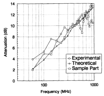
Spreading the clock frequency with a low frequency with a fixed or pseudo-random modulation (30 kHz, typically), such that the modulated signal is significantly wider than the resolution bandwidth of the measuring receiver or spectrum analyzer, effectively reduces the emissions from all signals synchronized with that clock oscillator. As can be observed in Figure 3, as the harmonic frequencies increase, the effective reduction in emission levels increases, as well.
Figure 3 – The experimental and theoretical improvement versus frequency at a 120 kHz bandwidth. Ref: Spread-Spectrum Clock Generation for the Reduction of Radiated Emissions, Hardin, Fessler, Bush, International Symposium on EMC, Aug. 1994.
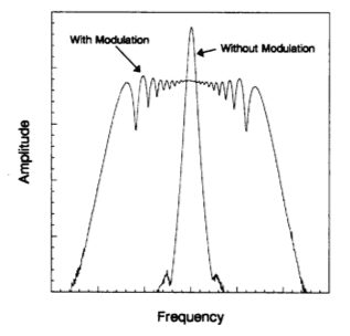
Figure 4 – Comparison of a non-spread clock signal with the spread signal. Ref: Spread-Spectrum Clock Generation for the Reduction of Radiated Emissions, Hardin, Fessler, Bush, International Symposium on EMC, Aug. 1994.
Figure 4 shows an example of a clock oscillator with the spreading turned on versus turned off. This example demonstrates “center spreading”, where the spread clock is equally spread above and below the non-spread clock signal. There can be timing issues with this method – especially, if the microprocessor or other digital devices are “overclocked” – that is, the non-spread clock frequency is already pushing past the manufacturers specified upper limit of the clocked devices.
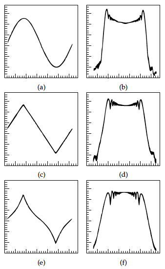
Figure 5 – The key to maximizing the attenuation of a clock signal is the modulating signal. Ref: Spread-Spectrum Clock Generation for the Reduction of Radiated Emissions, Hardin, Fessler, Bush, International Symposium on EMC, Aug. 1994.
For a sine wave modulation, the leading and trailing edges of the spread signal increase (“Batman” shape), due to the relative delay or time rate of change at the top and bottom of the sine wave. To improve the flatness of the spread signal, a triangle wave shape may be used, which includes much less delay at the top and bottom of the wave shape. Lexmark engineers improved that further by developing an exponential, or “Hershey Kiss” shaped waveform that provides best flatness in harmonic emissions. This wave shape, among other items, was what Lexmark ended up patenting. Many commercially available SSCG manufacturers license this modulation, but several also use triangular modulation.
Measurements of Spread Spectrum Clocking
I obtained an early spread spectrum clock demo board from IC Works several years ago, which I use as a demo of the technology during my EMC seminars. This board is nice in that the spread spectrum clocking may be easily turned on and off. For the purposes of this article, I measured the before and after spread clocking using the required EMI receiver bandwidth of 120 kHz versus frequency.
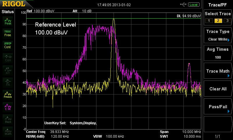
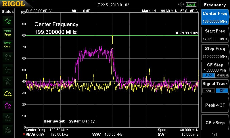
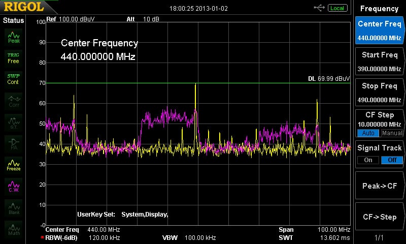
The sequence shows that as the harmonic order increases, so does the effective EMI reduction, because the higher order harmonics multiplies the spread. Starting with the fundamental clock frequency on this demo board of 40 MHz, we’ll compare with the 200 and 440 MHz harmonics. As you can see, as the frequency increases, the effective EMI reduction also increases, with 6, 12 and 15 dB reductions, respectively. I adjusted the span so that the relative width of the spread clock occupied approximately two divisions for ease of comparison. You can also observe the use of “down spreading” in frequency.
Figure 6 – The fundamental frequency of 40 MHz before and after SSCG is turned on (measured at 120 kHz bandwidth). Note: This is an example of a “down-spread” clock, which is a lot safer technique to use if you’re pushing the clocking limit of your digital devices (see Precautions section below).
Figure 7 – The harmonic at 200 MHz before and after SSCG is turned on (measured at 120 kHz bandwidth). Notice the effective EMI reduction has increased.
Figure 8 – The harmonic at 440 MHz before and after SSCG is turned on (measured at 120 kHz bandwidth). Notice the effective EMI reduction has increased even further.
Precautions
One problem presented by SSCG is that it can introduce timing skew and corresponding jitter in the system.
One of the significant disadvantages in using SSCG is that it cannot be used in systems where clock accuracy is of major concern; for example, Ethernet, CAN bus or critical timing applications. You need to take special care in specifying SSCGs and the spreading amount (and direction), as it can introduce substantial jitter to the clock signal. This jitter may affect system performance, causing critical setup and hold violations, higher bit error rates and PLL unlock issues.
Another area where extra precautions need to be taken is where the design includes a PLL downstream driven by the SSCG. A PLL exhibits the characteristics of a low-pass filter, which allows low-speed variations in the input frequency. Since the SSCG purposely modulates the clock, the PLL may have trouble maintaining lock. If the PLL bandwidth is too low, the PLL will not reliably track the clock, resulting in tracking skew and even more system jitter.
One of the first manufacturers to produce SSCG ICs was IC Works (acquired by Cypress Semiconductor Corporation in 1999). They were among the first to license the exponential (optimized) wave shape from Lexmark. The demo board I have used the W42C31-09 SSCG chip with down-spread technology.
Today, there are multiple manufacturers of SSCG ICs, including Analog Devices, Maxim, Linear Technology, ON Semiconductor, Fujitsu, Silicon Labs, Cypress Semiconductor, Mercury Crystal, NEL Frequency Controls, Xilinx and others.
SSCG – The Debate
While the FCC has officially blessed the technique and most all ITE and peripheral manufacturers have been using the technique for years, there are still those who question the validity as to whether EMI is really effectively improved – especially for the wider-bandwidth communications and broadcast systems used today. As you can see from the actual measurements (below), it does appear that widening the receiver or spectrum analyzer resolution bandwidth (RBW) reduces the effective EMI reduction towards zero. In fact, there is the illusion that at these wider bandwidths, the fundamental clock is simply sweeping or hopping back and forth at the modulation rate, such that the spectrum analyzer is “fooled” into measuring a lower than actual spread amplitude at 120 kHz RBW. This is, in fact, not quite correct, as I’ll explain further on.
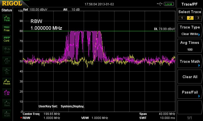
In comparing the same measured harmonic frequency of 200 MHz (Figure 7 above) with Figure 9 measured using a wider resolution bandwidth of 1 MHz, it really does appear there is no effective reduction at all and that the clock is simply “sweeping” in the frequency domain.
Figure 9 – The same 200 MHz harmonic as in Figure 7, but now measured at a 1 MHz bandwidth. Note the apparent spread clock reduction is zero – fooling critics into thinking the modulated clock is simply “sweeping” back and forth and that there’s no real reduction in EMI for wideband receiver technologies.
This seems to be the sticking point with most critics of the technology – that, in effect, for SSCG, the clock is really just “sweeping” or hopping back and forth in frequency according to the modulation applied and at the original amplitude so it seemingly allows product designers to exceed the radiated emissions limits by up to 20 dB, or so, worst case (assuming the spread signal is right at the limit and measured at 120 kHz bandwidth).
In April 2011, EE Times editor, Bill Schweber, published “Spread Spectrum Clock to reduce EMI: clever or cheat?” [Ref 12] where he brought up the general arguments on both sides. Excerpting from that article:
“One argument against using spread-spectrum is that you are very likely actually making your design “problem” into someone else’s. As you spread the energy, yes, you may meet a specification, but you also introduce the likelihood of unexpected problems when your spread energy mixes with as-yet unknown or undefined energy in other nearby or connected systems, each with their own frequencies and amplitudes. In short: “hey, I met the spec–after that, it’s your problem, not mine!”
Blogger, Michael Ossmann, echoes this sentiment in a blog posting August 18, 2011, “Spread Spectrum Clock Generation, Emissions, Security and You” [Ref 13].
“SSCG became popular, first with PC manufacturers and more recently for other electronic devices. The technique is used for one and (as far as I know) only one reason: to make it easier to pass electromagnetic compatibility (EMC) testing required by the FCC and other regulatory bodies around the world. EMC regulations are intended to limit RF emissions of electronic devices in order to avoid harmful interference to radio systems and other neighboring electronics. SSCG doesn’t do anything to reduce the radiated power of such emissions; it simply shifts their frequencies around so the EMC test equipment doesn’t register too high a power level at any one frequency. The electronics manufacturers are playing a shell game with their clock frequencies in order to evade detection.”
In addition, a study published in 2000 by the University of Hertfordshire indicates that broadband SSCG harmonics can cause disruption of DAB (Digital Audio Broadcasting) and DVB-T (Digital Video Broadcasting – Terrestrial) [Ref 14].
“DAB (Digital Audio Broadcasting) and DVB-T (Digital Video Broadcasting – Terrestrial) use COFDM (Carrier Orthogonal Frequency Division Multiplex). COFDM exhibits a threshold effect whereby interference is tolerated until the bit error rate exceeds a certain critical level. Beyond this threshold there is a rapid degradation leading to complete loss of all programmes carried by the DAB or DVB-T multiplex. A narrow band interfering signal such as a harmonic from a non-dithered clock or co-channel interference from an analogue VSB television signal may interfere with one or a small number of sub-carriers. This is generally tolerated but if a broad band signal interferes with a significant number of sub-carriers, this is likely to result in complete loss of service.”
“Tests have shown that an interfering source whose radiated emissions resemble broadband random noise has the greatest interference potential for DVB-T and DAB reception. The emissions from some types of DCO have an interference potential approaching that of random noise. If a radiated emission from such a DCO or one of its harmonics falls on a frequency that is being used for DVB-T reception, complete loss of service is likely.”
“In the context of interference investigation, a broad band interfering signal 20 dB below a COFDM broadcast signal (when both are measured in the same bandwidth) could cause loss of service but it would be difficult to locate the source of such a signal or even to prove its existence.”
On the other hand, in August 2001, Harry Skinner and Kevin Slattery (Intel Corporation) published experimental results showing this technique does actually reduce the risks of interference in electronic systems [Ref 15]. In their words, “The question should be: Does clock dithering reduce the interference potential of unintended radiators or by spreading the noise does it introduce a new means of upset in services that the regulations are intended to protect?” and “since the interference potential of a signal is dependent on the presence of an aggressor in a services operational frequency band for a length of time significant [with respect to] the integration time of the receiver, the frequency/time relationship introduced as a result of a modulation actually lowers the interference potential.”
Their experimental results measured the effect on an FM broadcast receiver (Sony Walkman) and indeed showed that spreading the energy over a 5 MHz bandwidth caused no apparent degradation in audio quality over a non-spread signal at the received frequency.
Later in 2003, Hardin, et al, published additional investigative results on interference to wideband digital systems [Ref 16]. The goal was to establish a method to measure interference potential using existing technologies as a reference level, and to determine the interference potential for digital television (DTV and DVB-T) receivers using both the modulated and unmodulated clock sources.
They defined a test procedure for evaluating the signal-to-interference margin for both DTV and DVB-T receivers. Because the COFDM transmission format used by DTV uses error-correction routines, it is much more tolerant of interfering signals than analog PAL TV receivers, to the tune of 16 dB better margins. Because interference problems in the field for PAL are being adequately managed under the current CISPR 22 and FCC Part 15 rules, Hardin concludes there is no need for further regulations for SSCG.
The Physics of SSCG
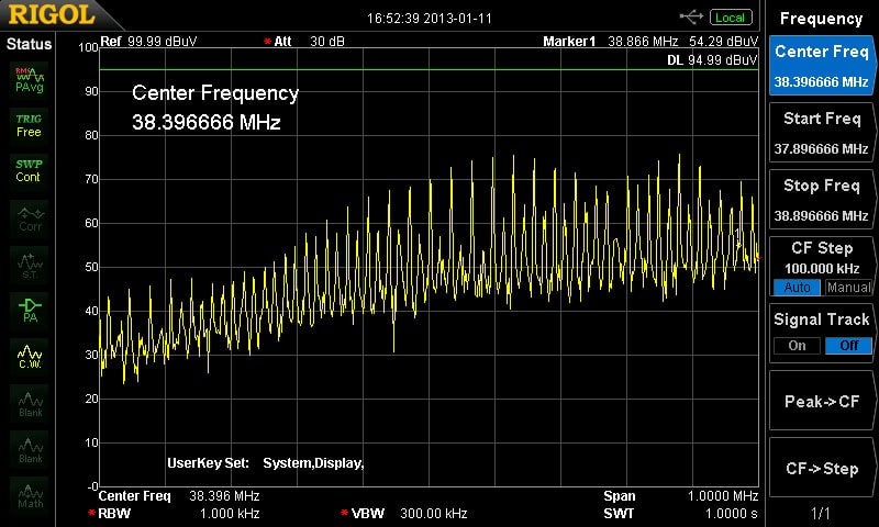
As I mentioned previously, SSCG is not simply sweeping or hopping the fundamental harmonic rapidly. If you were to examine the spread clock at a more reduced RBW, you would observe the spread signal is really comprised of an infinite series of fixed harmonics of the modulation frequency – in our example, 31.25 kHz (see Figure 10) with amplitudes gradually increasing as the fundamental frequency is approached. Most of these infinite harmonics will be hidden by the noise level of the analyzer until we start approaching the fundamental frequency and all its related higher-order harmonics.
Figure 10 – An expanded view of the 40 MHz spread spectrum signal tuned just below 40 MHz (38.4 MHz) so you can see the lower portion of the spread signal. In this case, the RBW is adjusted for 1 kHz. Notice the fixed – and reduced amplitude – series of 31.25 kHz harmonics. The fundamental 40 MHz fundamental signal is NOT being swept!
You can see that what is actually happening is not a sweeping fundamental clock, but a series of fixed (discrete) harmonics of 31.25 kHz spacing at a reduced amplitude from the non-spread fundamental. In this case, the non-spread fundamental at 40 MHz was about 95 dBuV (green display line) and the 31.25 kHz harmonics are reduced by about 18 dB (at 1 kHz RBW). You won’t be able to see this with the wider 120 kHz RBW, because at 120 kHz, there will be four to five discrete 31.25 kHz harmonics within the receiver pass band, which will add together and provide you an overall higher amplitude. As the RBW is increasingly widened (greater than the 31.25 kHz modulation), the discrete harmonics, when added together will approach the same amplitude as the non-spread fundamental because all of the discrete harmonics added together must give the same amplitude signal in the time domain as the non-modulated signal.
When assessing the actual physics of SSCG, it is important to keep the RBW (1 kHz, in this case) well below the modulation frequency of 31.25 kHz. The video BW should equal or exceed the RBW (300 kHz, used in this case). In general, spectrum analyzer plots with lower video bandwidths will give different amplitudes than a full compliance receiver because the filtering effect is different than in quasi-peak (QP) and Peak modes.
The harmonics we’re seeing are actually the result of the Fourier series of the modulated square wave f(x). The argument of the integral form of the Fourier series is the product of the time domain clock multiplied times the cos(nx) or sin(nx) functions.
In layman’s terms the likeness of f(x) to the cos(nx) or sin(nx) gives a higher value for the an and bn terms. The 40 MHz is the fundamental of the intended clock frequency with SSCG turned off, so one would expect the harmonics to only be at multiples of 40 MHz but we can also say that the 40 MHz non-spread clock is also periodic at 31.25 kHz as long as f(x)=f(x+1/31.25 kHz). This is saying the time shifted function by one period is the same as the original function. In this case all of the harmonics are zero from 31 kHz until you approach the 40 MHz fundamental (excluding some numerical errors). All of the amplitudes will be exactly the same at multiples of 40 MHz for calculating the harmonics with a period of 40 MHz. This is because the cos(2*pi*40 MHz*x) has a lot of likeness to the 40 MHz square wave and its harmonics.
Now let’s turn SSCG on. As you look at the harmonics of 31.25 kHz at <<40 MHz, the an and bn amplitudes are near zero since there is little likeness to a 40 MHz sine wave. As you approach n=1229 the Fourier series frequency is 31.25 kHz*1229 = 38.41 MHz (center frequency in Figure 10 above) then these frequencies are present part of the time in f(x), the modulated square wave. This gives rise to the harmonics you see on the spectrum analyzer. The harmonics will start to fall off again at frequencies higher than 40 MHz. If you were to add all the infinite harmonics in the time domain and with the correct phase (an inverse Fourier transform), you would reproduce the original modulated square wave clock.
Conclusion
While many engineers have been fooled into thinking SSCG is really “cheating” the standard, this is really not the case. The spread spectrum clock is not really “sweeping” back and forth at the same amplitude as the non-spread clock, but is really comprised of the Fourier series of lower-amplitude fixed-frequency harmonics of the modulating frequency of 31.25 kHz (in the case of this demo clock generator). Because it’s really the power density within the receiver pass band that causes interference, spreading the power through the use of SSCG tends to also reduce the risk of interference.
The fact there have been billions of products made with SSCG and that there have been few, if any, documented cases of SSCG being the root cause of interference problems, should provide a level of comfort to designers and those in standards enforcement.
SSCG References
- Richard Rhodes, Hedy’s Folly – The Life and Breakthrough Inventions of Hedy Lamarr”, describes her most interesting life as a silver screen star, mathematician and inventor.
- H. K. Markey, et al, Secret Communication System, U.S. Patent 2 292 387, August 11, 1942.
- Hardin, Fessler, and Bush, Spread-Spectrum Clock Generation for the Reduction of Radiated Emissions, International Symposium on EMC, August 1994.
- Hardin, Fessler and Bush, A Study of the Interference Potential of Spread Spectrum Clock Generation Techniques, IEEE International Symposium on EMC, August 1995.
- K. Hardin, et al., Spread Spectrum Clock Generator and Associated Method, U.S. Patent 5 488 627, January 30 1996.
- K. Hardin, et al., Spread Spectrum Clock Generator and Associated Method, U.S. Patent 5 867 524, January 30 1996.
- K. Hardin, Spread Spectrum Clock Generator, U.S. Patent 5 631 920, May 20 1997.
- K. Hardin, Variable Spread Spectrum Clock, U.S. Patent 6 167 103, December 26, 2000.
- K. Hardin, et al., Method and Apparatus for Compensating a Spread Spectrum Clock Generator, U.S. Patent 6 292 507, September 18, 2001
- Computer and Business Equipment Manufacturers Association (CBEMA), Document ESC5/77/29, “Limits and Methods of Measurement of Electromagnetic Emanations from Electronic Data Processing and Office Equipment”, 1977.
- J. P. Knapp, Letter from Federal Communications Commission to Donald R. Bush, Feb. 24, 1995.
- Bill Schweber, “Spread spectrum clock to reduce EMI: clever or cheat?”, April 27, 2012, http://www.eetimes.com/design/analog-design/4371865/Reducing-EMI-by-using-spread-spectrum-techniques
- Michael Mossman, Spread Spectrum Clock Generation, Emission Security, and You, http://ossmann.blogspot.com/2011/08/spread-spectrum-clock-generation.html
- Investigation into possible effects resulting from dithered clock oscillators on EMC measurements and interference to radio transmission systems, report to the Radiocommunications Agency by the University of Hertfordshire, March 2000.
- H.G. Skinner and K. P. Slattery, Why Spread Spectrum Clocking of Computing Devices is Not Cheating, IEEE International Symposium on EMC, August 2001.
- Hardin, Oglesbee and Fischer, Investigation Into the Interference Potential of Spread Spectrum Clock Generation to Broadband Digital Communications, IEEE Transactions on EMC, Vol. 45, No. 1, February 2003.
Other Current Discussions
Scope Junction: http://www.scopejunction.com/author.asp?section_id=1835&doc_id=253355&
LinkedIn group “EMC Experts”: http://www.linkedin.com/groupItem?view=&gid=1784463&type=member&item=181670231
Acknowledgement
I’d like to thank Ken Javor, owner, EMC Compliance, Dr. Keith Hardin, Lexmark International, Inc. and Dr. Robert Morrow (Morrow Technical Services) for their invaluable assistance in developing this article.
Author Bio
Kenneth Wyatt, Sr. EMC Engineer, Wyatt Technical Services, LLC, holds degrees in biology and electronic engineering and has worked as a product development engineer for 10 years at various aerospace firms on projects ranging from DC-DC power converters to RF and microwave systems for shipboard and space systems. For over 20 years, he has worked as an EMC engineer for Hewlett-Packard and Agilent Technologies in Colorado Springs. He has been an independent EMC consultant since 2008. A prolific author and presenter, he has written or presented topics including RF amplifier design, RF network analysis software, EMC design of products and use of harmonic comb generators for predicting shielding effectiveness. He has been published in magazines such as, RF Design, EMC Design & Test, Electronic Design, Microwave Journal, HP Journal, Safety & EMC (China), Interference Technology (ITEM), InCompliance Magazine, Test & Measurement World and several others. He currently writes The EMC Blog for Test & Measurement World.
Wyatt is a senior member of the IEEE and a long time member of the EMC Society where he serves as their official photographer. He is also a member of the dB Society and is a licensed amateur radio operator. He may be contacted at ken@emc-seminars.com.


