EMI testing in an unusual environment takes more time than testing in a lab environment.
Ed Kirchner, Harris Corporation, Melbourne, Floria, USA
Jeff Prosser, Rubicom Systems, Melbourne, Floria, USA
Grant Lohsen, Georgia Tech Research Institute, Atlanta, Georgia, USA
INTRODUCTION
A Harris Corporation test team recently performed a shielding effectiveness test on a welded steel enclosure. Program constraints dictated that the testing be done on the enclosure manufacturer’s factory floor, near Cincinnati, OH. As the Harris team was reminded, once a test moves from the controlled environment of the EMI lab or anechoic chamber, unusual things often happen. The EMI test engineer must be prepared for this. This article discusses the Harris team’s experience, and gives some general lessons learned for those situations where the EMI test environment is less than ideal.
THE TEST ARTICLE
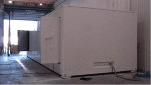
The article that the Harris team tested is a large welded enclosure. Its dimensions are 40’L X 14’W X 10.5’H. The enclosure is designed to house multiple racks of electronic equipment. A picture of the enclosure is given in Figure 1.
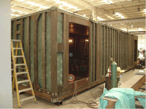
An important feature of the shelter design is its High-altitude Electromagnetic Pulse (HEMP) protection. The shelter incorporates a completely sealed steel HEMP liner, which is welded between the shelter’s outer and inner walls. The HEMP liner, coated with green primer, is shown in Figure 2.
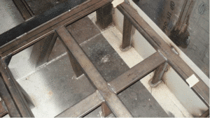
This design includes thousands of large and small welds, any of which could present a failure point for RF leakage. A picture showing a small sample of these welds is given in Figure 3. The performance of this HEMP liner, as well as three specially-designed shielded enclosure doors, was the focus of the Harris team’s test.
THE TEST SPECIFICATION AND METHODOLOGY
The program specification dictates that the shielded enclosure be tested in accordance with the shielding effectiveness levels and test methods described in the unclassified US military specification MIL-STD-188-125-1, “High-altitude Electromagnetic Pulse (HEMP) Protection for Ground-based C4I Facilities Performing Critical, Time-urgent Missions, Part 1 Fixed Facilities.”
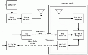
The methodology of the test is conceptually simple. A test signal of known amplitude is transmitted. Equipment inside the enclosure measures the received signal. The difference between the amplitudes of the transmitted and received signals provides the attenuation of the shielded enclosure. A representative drawing of the test configuration is given in Figure 4.
In accordance with the specification, measurements are taken at multiple points along all surfaces of the enclosure, including all sides, top and bottom. For this particular test, there were 24 test positions. Test methods required that at each position, both horizontal and vertical polarization measurements be taken for both E-field and H-field. Therefore, a total of 96 separate test runs were required. Although Harris has developed a proprietary method for automating the test process, each test run still took approximately 30 minutes. Therefore, even under the best possible scenarios, this test was a very labor intensive effort.
THE TEST ENVIRONMENT
As the Harris team planned for the test, we knew that one of the first challenges to face was the test environment. Ideally, a test of this nature would be performed in the controlled environment of a specialized test facility, such as a large anechoic chamber. In this case, the test had to be performed on the very busy manufacturing floor of the enclosure subcontractor (see Figure 5).
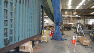
In addition to the cost and schedule savings gained from not having to move the shelter to a special facility, the decision to test at the subcontractor facility made very practical sense. The Harris test effort would be completed in two stages: a pre-test, which would evaluate the shielding effectiveness of the HEMP liner before the final outer enclosure skins were installed, and a final test on the completed chamber.
The intent of the pre-test was to allow easier rework to the HEMP liner in cases where unacceptable RF leakage was measured. Rework on the completed enclosure was deemed to be too risky from both cost and schedule perspectives. Testing on the shop floor enabled any rework on the HEMP liner to occur as soon as outages were measured.
Unfortunately, the decision to perform testing on the shop floor brought some unique test variables into play:
- A noisy ambient RF environment, resulting from constant use of broadband noise sources such as arc-welders, motors, and fans on the shop floor
- Unknown quality of shop floor electrical power
- Special considerations for safety of personnel working in the area
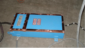
The first effect of the test variables was mitigated by the proprietary Harris test process, which includes specialized software that greatly reduces the effect of ambient noise. The electrical power issue was handled through the use of an EMI power filter, pictured in Figure 6. The EMI filter was provided to the subcontractor by Harris. The subcontractor wired the unit for use in the test. As will be discussed below, introducing the EMI filter into the test configuration was not without complications.
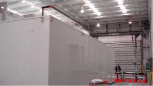
Safety issues were handled by transmitting an RF signal at the lowest possible power level that allowed the required dynamic range to be achieved. The level was far below the limits given in ANSI/IEEE C95.1-1992, the industrial specification for Radiation Hazard (RADHAZ). In addition, safety equipment such as cones and perimeter tape was used to cordon off the test area. In spite of this, there were still incidents of non-test personnel intruding on the test area perimeter (see Figure 7). This meant that the test team had to be diligent in policing the area, and diplomatic in approaching people unknowingly disturbing the test.
THE TEST
As mentioned above, the shielding effectiveness testing was accomplished in two stages: first, the “Pre-test”, with the HEMP liner complete, but no outer skins in place, and second, the “Final test” in the complete configuration. The original schedule had two separate week-long blocks of time allocated for each test. Prior to the Harris test team’s arrival, the enclosure manufacturer successfully performed a Shielding Effectiveness Leak Detection System (SELDS) test to assess the quality of the welding. This is an industry-standard test to assess the RF integrity of welds, and is beneficial to use prior to any shielding test. Basically, the SELDS equipment places a current on the skin of the shelter and a tone is generated within the shelter at weld RF leak points. It can be quite accurate, but care must be given to setting up the equipment properly. Even more importantly, the SELDS tester must painstakingly go over each weld in the shelter. In the best case, the welds being assessed are long and continuous. Unfortunately, the shelter we tested was constructed using thousands of small, discrete welds which were very easy to miss with the SELDS test set. The results of the SELDS testing were not intended to be conclusive, but instead were used to give the Harris team a high level of confidence that the enclosure was ready for the qualification shielding effectiveness testing.
“PRE-TEST” EXPERIENCES
The Harris test team arrived on site, set up our equipment, and began the test. Immediately, we began to see a broad set of failures, i.e. apparent RF leaks in the welded shielded enclosure. Since the SELDS test results indicated that the shelter shielding should have been fairly tight (if anything, we expected “spot frequency” failures, not broad failures indicating large leaks), we suspected the first arrival of “EMI gremlins”. EMI gremlins cause those pesky problems that all experienced EMI engineers know will pop up out of nowhere to drive us crazy, but – let’s be completely honest here – also provide the challenge that EMI engineers love. In this case, the source of the problem was found to be the EMI filter discussed above. The filter enclosure was not tight enough, causing enough noise from getting into the very sensitive test receiver chain to cause phantom failures. Time to get out the copper tape – one of an EMI engineer’s most important tools, as the picture in Figure 7 indicates. Sealing the filter enclosure with copper tape eliminated the problem.
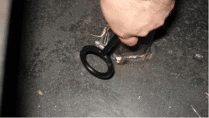
After the filter issue was resolved, the test proceeded as planned. The shelter was found to be performing well, with the occasional (and expected) “spot frequency” failure. In these cases, hand probing (see Figure 8 ) was used to “sniff” out the specific leaking weld. The sniffing process was effective, but very time consuming. These welds were repaired by the manufacturing team, and retested. The test team methodically moved from test location to test location, and settled into the routine of testing.
The routine came to a screeching halt when the test team arrived at the front of the shelter. All of a sudden, two prominent failures, one centered around 36 MHz, and the other at 44 MHz, showed up at four of the test locations. At first glance, this indicated major weld leaks. The team began the very slow sniffing process – assessing each suspect weld one at a time. Over a period of several days, the team found about 15 welds that seemed suspect. These were repaired, and the team began to retest the failed test frequencies with a great deal of confidence.
Confidence quickly turned to despair – the failures were not resolved at all! Major teeth gnashing and head scratching ensued, but the experience of the test team prevented full-bore panic from setting in. The team fell back on its extensive experience, and began a methodical assessment of “what ifs”. Failure mechanism theories were developed, and each was evaluated and tested one-by-one. Eventually, two culprits were discovered.
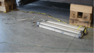
First of all, an innocent-looking string of fluorescent work lights were found to be acting as a 36 MHz antenna inside of the enclosure. Note that these lights were not plugged in during the test; they were simply placed in the enclosure in a geometry that, upon further inspection, made a surprisingly efficient dipole antenna. We found that energy impingent on the shelter HEMP liner was coupling onto the unshielded wire of the light string, and was being re-radiated within the shelter. The test receiver antenna was picking this energy up, and indicating our phantom failures (see Figure 9 – look closely for the unlit florescent light string on the back wall).
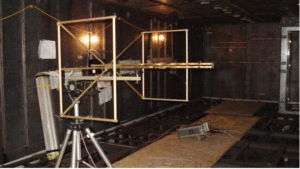
Once the offending lights were removed, (see Figure 10), the 36 MHz problem went away.
The 44 MHz problem, most infuriatingly, was still present. However, bolstered by our success in resolving the light string problem we went back to our list of “EMI gremlin” possibilities.
This time, we took a closer look at the electrical box and cabling, provided by the shelter manufacturer, which brought the filtered power into the shelter. Sure enough, RF probing of the electrical box and cabling indicated emissions in the frequency range of interest. We discovered that grounding the electrical box to the metal structure of the enclosure, as opposed to resting it on the plywood work floors for convenient access, eliminated the problem (see Figure 11). Although we were not able to disassemble the electrical box for inspection (since it was not our asset), we believe that there was an ungrounded safety wire in the assembly that was acting as a 44 MHz antenna, coupling energy from the HEMP liner wall, and re-radiating it within the shelter.
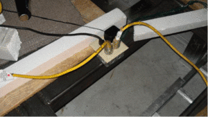
Finally, all gremlins were eliminated, and the pre-test was completed. However, because of the challenges that had to be overcome, the test, which was originally scheduled for one week, took a total of three weeks! The tired, but satisfied, EMI test team went home, and the shelter was completed by the manufacturer.
“FINAL TEST” EXPERIENCES
Approximately six weeks after the pre-test, the EMI test team returned to Cincinnati to perform the final test. This time, the team was very conscious from the outset on keeping the test configuration as “clean” as possible. The final test was completed with no difficulties, and within the one week scheduled for the test. The “smooth sailing” of this test was undoubtedly a product of the trials and tribulations suffered in the pre-test. The fully compliant completed HEMP enclosure was soon after delivered to Harris.
LESSONS LEARNED/CONCLUSION
The major lesson that the Harris team learned in their experiences was that EMI testing in an unusual environment takes more time than testing in a lab environment. In addition to the major technical challenges discussed above, there were also unexpected delays resulting from test equipment shipping problems, test equipment failures, and schedule/resource conflicts with other activities on the manufacturing floor. These should be anticipated, and built into the test schedule.
The second major lesson is that the probability of “EMI gremlins” showing up is much higher in an uncontrolled environment. This should be expected, and the EMI engineer should prepare for it. Review your personal set of “lessons learned”, talk to your colleagues, and research other resources (such as this publication) to learn from the experiences of others. While the specifics of each situation may be unique, it is unlikely that a problem is so unique that a similar situation hasn’t been tackled before.
As we found, the power and grounding set-up in a non-controlled environment is a very likely source of problems. Using an automated system on AC power, the EMI engineer must ensure that the power is filtered and the outlet being used within the enclosure is properly grounded. Poor filtering can cause the transmit signal to enter the shelter via the AC power, leading to a false indication of a test failure. Without proper grounding, the EMI engineer may see noise inside the shelter caused by conducted emissions radiating from the power lines of the receive test equipment. Other false failures can be due to poor EMI gasketing on the clean side of the filter and improper terminations on shielded conduit between the shelter and the filter. Both of these items should be checked prior to testing to avoid unnecessary delays and regression testing.
As we found with the fluorescent light string, eliminating unnecessary wiring and other metallic items from the test article configuration will greatly reduce the chance that “phantom” signals can be generated or re-radiated and detected as failures. Even if these items cannot be readily removed at the onset of the test, the EMI should note possible “suspects” in the event that unusual problems do arise.
EMI testing in an uncontrolled environment invariably introduces complications into the test process. However, these complications are not insurmountable, and the successful completion of a test in such an environment can ultimately be a rewarding high point in the EMI engineer’s career.
ABOUT THE AUTHORS
Ed Kirchner is a Senior Systems Engineer at Harris Corporation, Melbourne, FL. He is an iNarte certified EMC Engineer, and can be reached ekirchne@harris.com.
Grant Lohsen is a Research Engineer at GTRI, Atlanta, GA, and can be reached at wlohsen@gmail.com.
Jeff Prosser is General Manager of Rubicom Systems, Melbourne, FL. He can be reached at jprosser@rubicomtestlab.com.
