The airframe of an aircraft can provide some measure of shielding against high-intensity radiated fields (HIRF), but this is compromised by doors, windows, seams, access panels and components interfaced to the airframe such as antennas used for communication and navigation. Composite materials are increasingly used in aeronautical applications due to their relatively light weight, but their unique electromagnetic properties create additional challenges for maintaining shielding integrity. This article will explore the electromagnetic simulation of shields at both the component and airframe level, while demonstrating how special modeling techniques applied in the 3D TLM method can be used to improve the efficiency of capturing the important coupling mechanisms.
Introduction
Aircraft are subject to a range of environmental electromagnetic effects (E3), such as lightning strikes, electromagnetic pulses (EMP) and high-intensity radiated fields (HIRF), which can pose a risk to the safe performance of avionics. Shielding can mitigate these risks and protect electronic systems. However, shielding effectiveness may be compromised by aperture leakage or diffusion, allowing fields to penetrate.
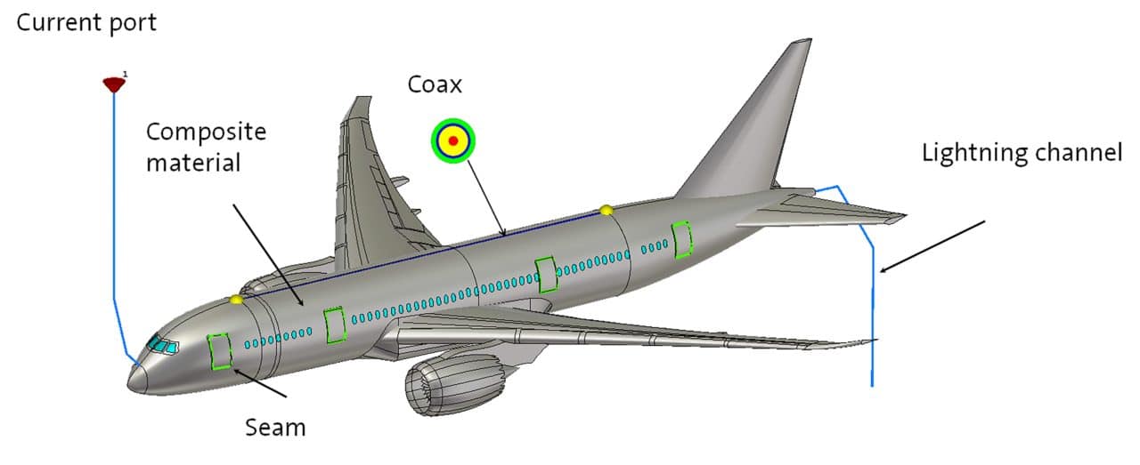
This means that when developing shielding, the aircraft engineer has to balance several contradictory design requirements. In the name of weight reduction, material use should be minimized, but making shields thinner can increase leakage. This is made more complex by the increasing use of lightweight composite materials in the airframe, which have different electromagnetic properties to the conventionally used metals, and by the need to include doors, windows and cables in the aircraft (Figure 1).
Electromagnetic simulation offers an effective way to investigate these effects during the design process. Simulation allows the effect different configurations and material properties to be assessed easily and field visualization helps engineers to identify the coupling paths that lead to field penetration.
E3 scenarios
There are a range of different scenarios that need to be considered for shielding analysis, including HIRF, EMP, lightning strike, electrostatic discharge (ESD) and radiated emissions from onboard devices. With the right simulation setup, these can all be assessed with virtual prototypes.
As these are all usually broadband or transient phenomena, a time domain approach is usually the best choice. With time domain simulation, the entire frequency spectrum of interest can be covered by a single simulation. External fields can be modeled using plane waves for external effects such as HIRF and EMP, or using near field sources drawn from simulation or measured data and placed within the aircraft. Using field sources can reduce the complexity of simulation, replacing detailed models with more efficient representations of the source of emissions.
For lightning strike analysis, lightning channels can be modeled as wires connecting the aircraft to a current source. Lightning attachment zones can first be predicted using electrostatic simulation [1].
Skin effect and composite materials
The penetration of fields through solid material is limited by the skin effect. High frequency current does not flow uniformly throughout the cross-sectional area of a conductor. Instead, the current flows in a thin layer just underneath the surface, and the thickness of the conduction layer is defined by the skin depth at that frequency. The skin depth is defined as the depth at which field intensity has reduced to 1/e or 37%.
In metals, which have high conductivity and often also high permeability, the skin depth is very short. Aluminum has a conductivity of around 35 MS/m, and the skin depth at 1 MHz is around 0.085 mm. At these frequencies, any diffusion through typical metal thicknesses would be negligible.
However, because of their light weight and strength, carbon fiber composite (CFC) materials are increasingly used in aircraft, with some modern airliners being over 50% composites. These materials are significantly less conductive, and provide less shielding. Carbon fiber has a conductivity of around 104 to 105 S/m with corresponding skin depths at 1 MHz ranging between 1.6 and 5 mm –orders of magnitude greater than aluminum. This will result in significantly greater field diffusion through the material.
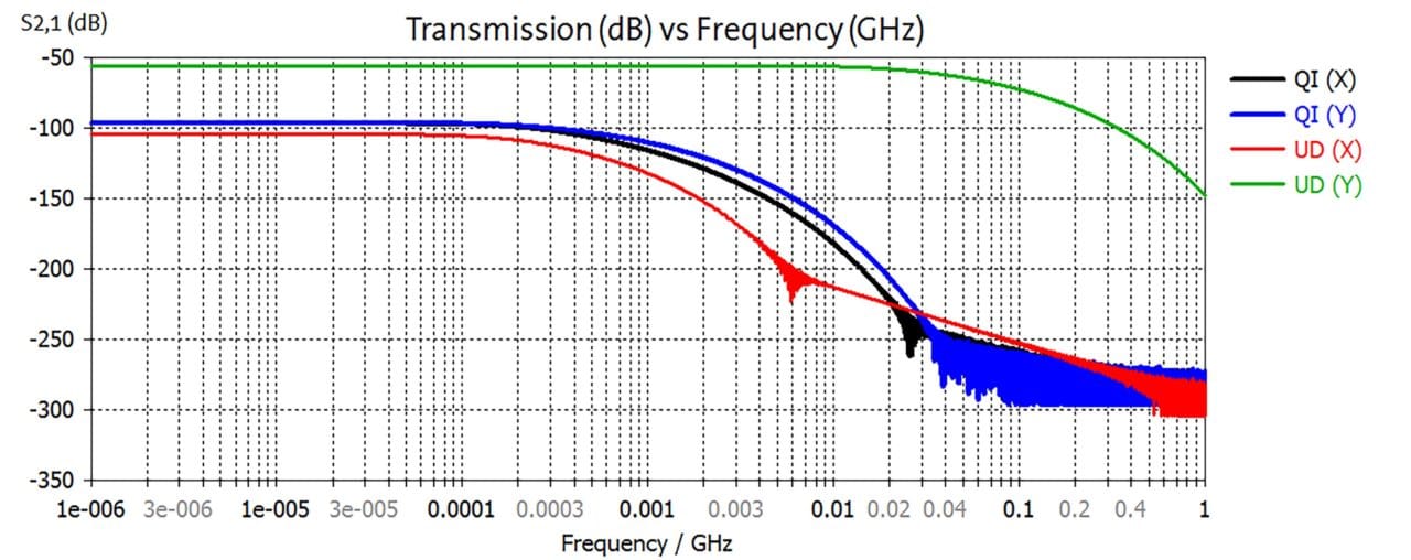
An additional complication is that CFC materials often have a complex structure giving them anisotropic EM properties. Multiple layers of fibers are stacked to form a laminate, and the fiber direction can vary from ply to ply. Figure 2 shows how this can significantly affect the shielding performance of the material. In this simulation, a broadband diagonally polarized plane wave is incident on a sheet of CFC laminate. In one variant, the fibers in each ply are all aligned in the same direction (uni-directional or UD). In the other, each layer is rotated sequentially (quasi-isotropic or QI). As the results show, the QI laminate attenuated the fields by a similar amount in both x and y directions. However, the UD laminate shows very different results, with around a 50 dB difference in field transmission between the two components.
Because CFC materials offer less shielding, especially at low frequencies, they can be supplemented with wire mesh. This creates a Faraday cage that can significantly increase shielding and lightning protection. Both CFCs and wire meshes contain fine detail, and this can be simulated much more effectively using equivalent models rather than modeling individual wires or fibers. The examples in this article were simulated using the multi-layer (stacked) thin panel material and wire mesh material in CST STUDIO SUITE®. These offer extremely close agreement to more detailed models and to the expected analytical results (Figure 3).

Fine details
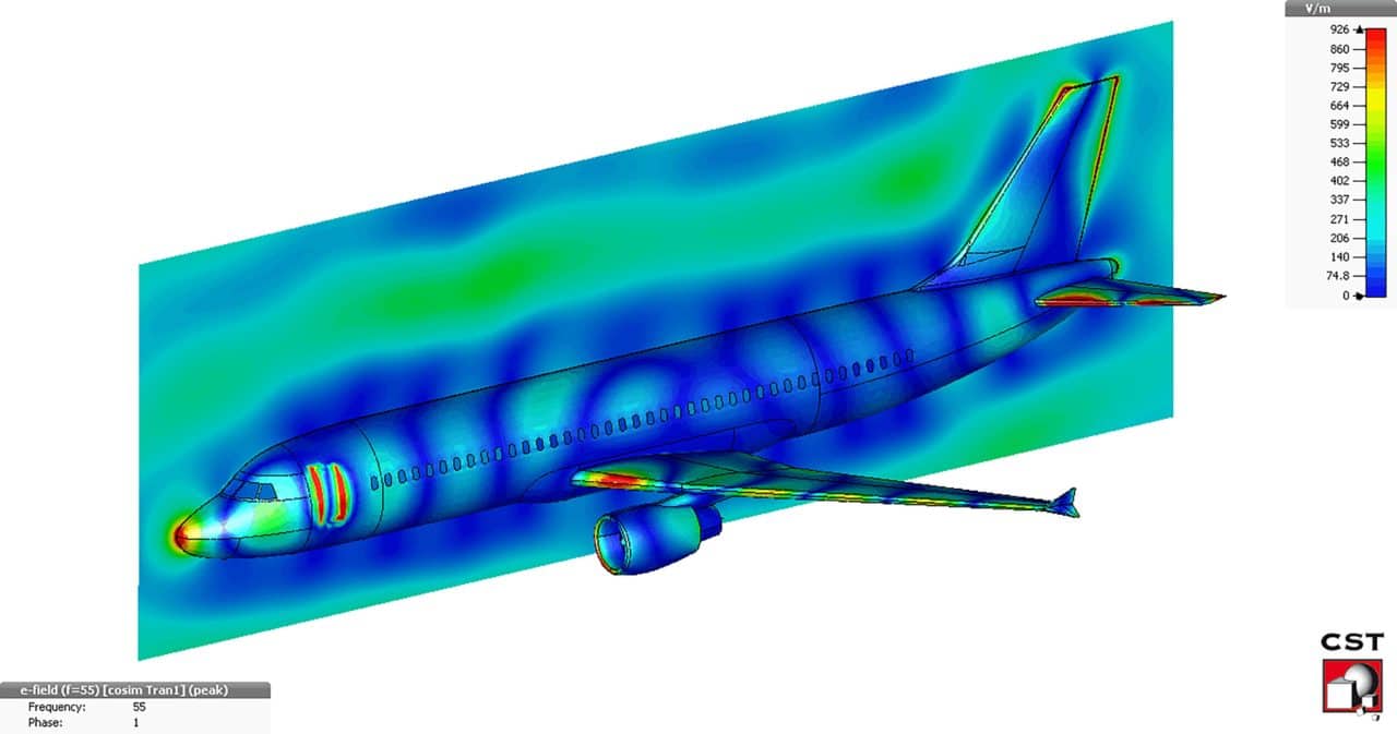
Any practical shield will have some gaps in it; for example, vents, windows, joints and seams. Fields can penetrate through these – even very fine seams can compromise shielding if the length of the seam corresponds to the resonant frequency of the incident radiation (Figure 4). This means that modeling all this fine detail is essential for the accurate simulation of shielding performance, and special simulation methods are required in order to perform these calculations in a practical length of time.
For E3 simulations, the time domain transmission line matrix (TLM) solver is often a very efficient tool. The TLM solver is broadband, and it can also model transient effects such as lightning strikes directly. In addition, the TLM solver also supports octree meshing, with a very fine mesh around small details and a sparser mesh in open space. This can significantly reduce simulation run times compared to other solver types, especially when combined with high-performance GPU computing.
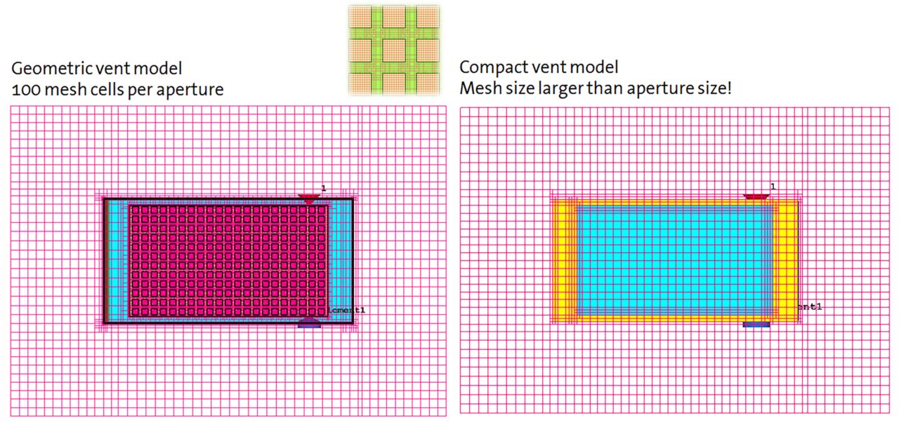
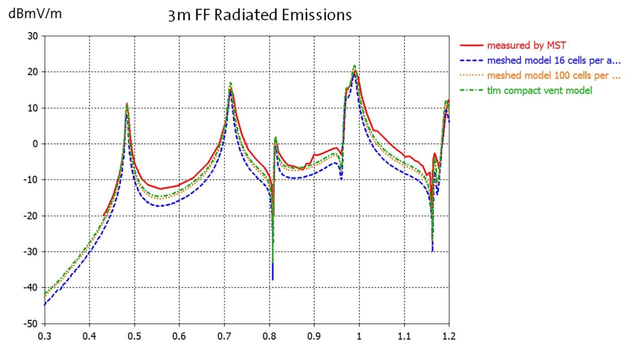
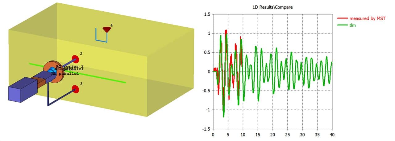
In addition, many fine details from the CAD data can be replaced with compact models. For example, simulating the shielding performance of an avionics box that includes a ventilation panel in 3D would mean that each individual hole needs to be modeled and meshed, increasing simulation time. The vent can therefore be replaced by a compact model containing an analytic representation of the vent’s transmission properties, which is much faster to simulate – the mesh can be larger than the aperture size, which not only reduces the number of mesh cells needed but also allows a larger time step for a shorter simulation. Figure 5 shows the implementation of a compact vent model for simulating an electronics enclosure. Using the compact model reduced simulation times by 25% compared to a 3D model with a rough mesh, and by 85% compared to a more accurate fine mesh. The simulated compact model results also agreed closely with measured results, demonstrating the viability of simulation for virtual prototyping.

Conclusion
Implementing simulation in the design process gives engineers greater capacity to analyze and optimize EM shielding at an early stage. Simulated and measured results complement each other: replicating common test scenarios with virtual prototypes allows changes to be implemented and assessed without the time and money costs associated with a physical prototype.
References
- Kunze, Marco, “Supporting Future Aircraft Certifications with EM Simulations”, In Compliance, Dec 2015
- F. Centola et al., “ESD Excitation Model for Susceptibility Study,” Proceedings of the IEEE International Symposium on EMC, Aug 2003
- Li, Min; Nuebel, J.; Drewniak, James L.; Hubing, Todd H.; DuBroff, Richard E.; and Van Doren, Thomas, “EMI reduction from airflow aperture arrays using dual-perforated screens and loss“, IEEE Transactions on EMC, Aug 2000
