Studies suggest that models based on only the metallic parts of a vehicle can provide useful data for predicting the electromagnetic performance of complex systems such as vehicles.
Alastair R. Ruddle, Ph.D., MIRA Limited, Nuneaton, UK
Numerical modeling is an increasingly popular approach for investigating electromagnetic issues in complex systems. Possible applications include the investigation of EMC characteristics, radio propagation issues, installed antenna performance, and human exposure to electromagnetic fields. However, building practicable models of real-world systems inevitably requires a high degree of approximation, so it is important to have an understanding of what can reasonably be neglected in such models, under what circumstances, and what the implications might be.
An approximation that is commonly employed is to ignore the many dielectric components that are usually present in the complete system. In vehicle models, for example, components such as the window glazing, seat cushions, the dashboard, carpets, and other internal trim are often omitted. In all numerical modeling techniques, the inclusion of dielectric materials requires additional or denser mesh; and for some methods, the associated computational cost can be very significant. Furthermore, geometrical data and electrical properties for the dielectric parts may not be readily available. A metal-only vehicle model is certainly quicker and simpler to build and is more efficient in terms of computing time and memory requirements, but is it adequate for the intended purpose?


Such a model could perhaps be justified on the grounds that it provides a “worst-case” configuration since the dielectric models provide loss mechanisms that reduce field levels. For example, it has been reported that simulations based on a metal-only vehicle overestimate the measured internal field by around 6 dB for an onboard GSM antenna operating at around 900 MHz.[1] A further argument for neglecting the dielectric parts at lower frequencies is that they are often electrically thin and are, therefore, effectively transparent. Validation studies based on metal-only car models agree well with measurements on complete vehicles for frequencies up to 1 GHz.[2, 3] In addition, comparative measurements up to 1 GHz[4] also show relatively small differences caused by dielectric parts that can be easily removed, such as the door windows and seat cushions.
A passenger car is sufficiently compact for comparison of a number of simulations, each based on slightly different model variants, to be practicable up to 2 GHz with models that include dielectric materials. Numerical and analytical models have, therefore, been used to investigate the likely impact of representative dielectric materials on the electromagnetic field distributions inside the passenger compartment of a car. The results of this work may also be of relevance for models of larger vehicles, including ships, trains, and aircraft, as well as to other resonant environments such as buildings.
NUMERICAL VEHICLE MODELS
To investigate the impact of typical vehicle trim materials, a series of staged numerical models was constructed, with material content as follows:
- metal only (case A);
- metal and glass (case B);
- metal, glass, and foam (case C);
- metal, glass, foam, and thin plastics (case D).


The simulations were carried out using a full-wave 3D transmission line matrix field solver (Microstripes[5]), and the numerical models were derived from 3D geometry for a passenger car. In this study, the impact of the dielectrics is evaluated in terms of the spatial field distribution over the region of the passenger compartment where the occupants may be located. The data were extracted from the models for more than two million points at selected frequencies up to 2 GHz.
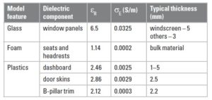
The relative permittivity (εx) and electrical conductivity (σE) that were used to represent the different material types are detailed in Table 1, based on measurements of representative samples at 3 GHz [6], along with their physical thickness.
IMPACT OF DIELECTRICS ON FIELD POPULATIONS
The impact of the dielectric materials on the internal electric field populations under plane wave illumination from the front of the car models is illustrated in Figure 1, where the presence of the glazing clearly shifts the peak of the distribution to lower field levels for horizontal polarization. The impact of the glazing on horizontal field coupling is reduced at lower frequencies, but the results for vertical polarization (Figure 2) do not show this effect. Still, the foam and plastic materials do not have a significant additional impact on the field populations for either polarization.
The field distributions resulting under excitation from internal sources have also been investigated, using simple horizontal and vertical dipole antennas located in the vicinity of the rear seat. In these cases (Figures 3 and 4), there is not a significant difference in behavior between the two source polarizations, and neither the glass nor the foam and plastic materials have much impact on the field populations.
Locally, the surfaces of large window panels are approximately flat, and their impact on propagation through the glazing can be estimated from analytical models for plane wave interactions with planar dielectric multilayers.[7]
Simple calculations based on the transmittance of a slab of dielectric illuminated at normal incidence suggest that for typical car window dimensions (i.e., 3–6 mm thick) the glazing is effectively transparent below 1 GHz. At higher frequencies, however, the thickness can become resonant, resulting in much higher reflections at some frequencies, depending on material properties and construction details. Nonetheless, field coupling into the passenger compartment at lower frequencies may also be radically different for horizontally and vertically polarized external plane wave sources at non-normal incidence.
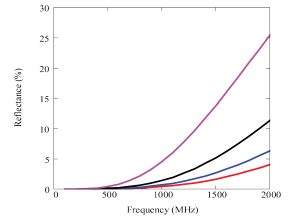
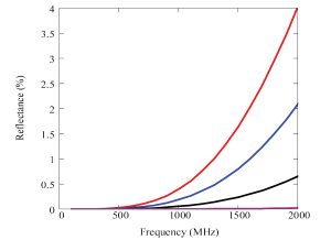
This is illustrated in Figures 5 and 6, which show the reflectance for a lossless planar dielectric slab under illumination by horizontal and vertical plane waves at angles of incidence ranging from 0° (normal incidence) up to 60° (representing a windscreen illuminated from the front by a distant source). In the latter case, the reflectance for a horizontally polarized source is around 5 percent at 1 GHz, rising to more than 25 percent at 2 GHz—while for vertical polarization the reflectance is negligible. At a planar interface between two dielectrics, the reflectance for vertical polarization becomes negligible at the Brewster angle. This phenomenon, therefore, would seem to be the most likely cause for the differences in the impact of the glass in the models for the two polarizations.


For the internal sources, the glazing is illuminated at a wide range of angles of incidence as the radiated fields are scattered around the interior of the passenger compartment. Under external plane wave illumination a similar process also takes place. Still, the total power coupled into the vehicle interior is smaller for horizontal plane waves incident from the front of the vehicle when glass is present, resulting in lower internal field strengths for those cases that include glazing.
IMPACT OF DIELECTRICS ON AVERAGE FIELD STRENGTHS
Average internal electric fields obtained under external plane wave illumination from the front of the car are summarized in Figures 7 and 8 (at 1 W/m2 incident power density). These results show a clear difference between the two polarizations. This difference is due in part to the differences in coupling through the glass outlined above, but it also reflects differences in the response of the metal vehicle structure to the two polarizations, which reduce as the frequency increases. (The metal-only results converge by 3 GHz). Apart from these effects, however, the average field values are largely unaffected by the additional dielectric content of the models.
Above 1 GHz, the vehicle interior is sufficiently large (relative to the wavelength) to exploit power balance methods[8] to estimate the average internal field strengths and population distributions from simple analytical models based on very limited geometrical data.
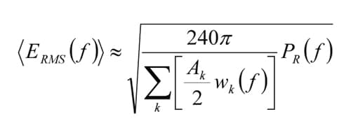
Assuming that the windows represent the dominant source of loss for the system, and that they are also electrically large at the frequencies of interest, the average field strength can be estimated from the window areas, glazing construction, and the power coupled into the vehicle interior.[9] For windows of area Ak, the RMS electric field strength averaged over the volume of the cavity at frequency ƒ is approximately:
PR(ƒ) is the power coupled into the interior, and the wk(ƒ) are frequency dependent aperture weighting factors that represent the properties of the glazing used in each window k. These aperture weighting factors are determined [9] from:
θ is the angle of incidence, while Tk⊥ (ƒ,θ) and Tk||(ƒ,θ) represent the transmittances for the flat glazing panel in aperture k with the incident field polarizations perpendicular and parallel to the plane of incidence, respectively.
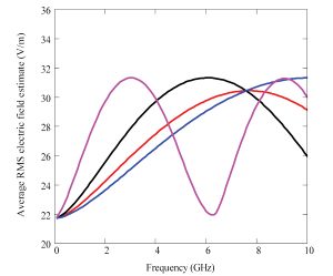
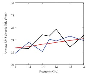
Using these analytical approximations, it is possible to predict the average internal electric field strengths caused by internal sources at microwave frequencies (Figure 9) for vehicles with various glazing configurations. These very simple estimates are found to compare well with average field values derived from the 3D numerical models (Figure 10).

LOCAL FIELD DIFFERENCES CAUSED BY DIELECTRICS
Cumulative distributions for relative errors between the metal-only model and those with different dielectric content give an indication of the impact of these materials on local field strengths. Sample results for external vertical plane wave illumination are illustrated in Figures 11 and 12, showing that the differences rise from less than 40 percent at 70 MHz to more than 100 percent at 400 MHz.
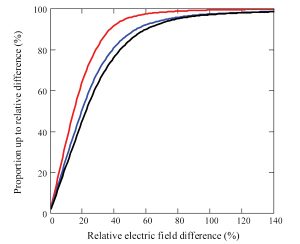
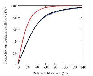
Sample results for an internal horizontal source operating at frequencies in the range 1–2 GHz (Figures 13 and 14) also indicate that the local differences continue to increase at higher frequencies. Similar results are obtained for the vertical dipole and for the magnetic field components.
CONCLUSIONS
Simple analytical models suggest that car window glazing is likely to become increasingly important for in-vehicle fields at frequencies above 1 GHz and may be significant for external plane wave illumination configurations with non-normal incidence at lower frequencies. Numerical models based on 3D vehicle geometry also support these conclusions.

In addition, the results of the 3D simulations indicate that foam and plastic materials found in the interiors of passenger cars do not have a significant impact on the statistical properties of the internal field distributions for frequencies up to 2 GHz. Nonetheless, the simulations suggest that the presence of dielectric materials can result in significant changes in the local field strength at individual points (with relative differences of >100 percent), and that these changes become greater at higher frequencies.
The results obtained from the models investigated in this work do not show the increased losses[1] reported for complete vehicles relative to the metal body-shell. However, the models used in this work do not include all of the components found in a complete car. Measured dielectric samples harvested from cars[6] usually exhibit low to medium loss factors, although rubber is sufficiently lossy to offer some potential for helping to reduce undesirable field levels.[6] It is possible that the larger numbers of low loss materials that are present in cars, perhaps combined with higher loss components such as rubber door seals and the vehicle electrical system, may account for the greater losses reported for the complete car.
For human exposure assessments, the field statistics are of greater interest than the exact details of the field at individual points.[10, 11] For EMC purposes, the field in more specific regions is generally of greater interest, but the detailed field distribution is likely to vary with illumination configuration. Since real-world threats normally encompass a wide range of possible illumination configurations, the use of statistical field measures has also been investigated for immunity applications.[12, 13]
Consequently, the results of this study suggest that models based on the metallic parts of a vehicle, possibly augmented with window glazing (depending on the frequency and source configuration under investigation) can provide useful data for predicting the electromagnetic performance of complex systems such as vehicles. Furthermore, for electrically large systems (i.e., large structures and/or high frequencies), which are less amenable to numerical modeling, analytical models based on the power balance approach show considerable promise as a more efficient method for obtaining statistical measures for the field distributions.
Power balance calculations require very little detailed information about the geometry of the target environment, and their computing requirements are insignificant compared to deterministic 3D numerical models. Thus, the benefits of this approach include limiting the need for access to comprehensive CAD data, thus avoiding the associated difficulties of building topologically coherent 3D models and generating mesh of suitable quality—as well as eliminating the need to process large data sets obtained from many lengthy simulations on high-end computer workstations. Possible applications range from larger road vehicles, such as trucks and buses, to other resonant environments such as ships, trains, aircraft, and buildings.
ACKNOWLEDGEMENTS
The work outlined above was carried out as part of SEFERE[14], a collaborative research project that is supported by the UK’s Technology Strategy Board (contract TP/3/DSM/6/I/15266) and Engineering and Physical Sciences Research Council (grant EP/D033187/1). The project consortium includes MIRA Limited (coordinator), ARUP Communications, BAE Systems, Harada Industries Europe, Jaguar Cars, the University of Sheffield, UK National Policing Improvements Agency, and Volvo Car Corporation (Sweden).
REFERENCES
1. M. Klingler and A. Lecca, “Comparison between simulations and measurements of the fields created by a mounted GSM antenna using a car body instead of an entire vehicle,” Proc. 7th European Symposium on EMC, Barcelona, Spain, September 2006, pp. 732–742.
2. A.R. Ruddle, X. Ferrières, J.–P. Parmantier and D.D. Ward, “Experimental validation of time-domain electromagnetic models for field coupling into the interior of a vehicle due to a nearby broadband antenna,” IEE Proc. Science, Measurement and Technology, Vol. 151, No. 6, November 2004, pp. 430–433.
3. A.R. Ruddle, “Validation of predicted 3D electromagnetic field distributions due to vehicle mounted antennas against measured 2D external electric field mapping,” IET Science, Measurement and Technology, Vol. 1, No. 1, January 2007, pp. 71–75.
4. A.R. Ruddle, “Measured impact of vehicle seats and glazing on the coupling of electromagnetic fields into vehicles and their wiring harnesses,” Proc. 15th Zurich EMC Symposium, Zurich, Switzerland, February 2003
5. D.P. Johns, R. Scaramuzza and A.J. Wlodarczyk, “Micro-Stripes – microwave design tool based on 3D-TLM,” Proc. 1st International Workshop on Transmission Line Matrix (TLM) Modeling – Theory and Applications, Victoria, Canada, August 1995, pp. 169–177.
6. A.R. Ruddle, H. Zhang, L. Low, J. Rigelsford, and R.J. Langley, “Numerical investigation of the impact of dielectric components on electromagnetic field distributions in the passenger compartment of a vehicle,” Proc. 20th Zurich EMC Symposium, Zurich, Switzerland, January 2009, pp. 213–216.
7. H.M. Liddel, “Computer-aided Techniques for the Design of Multilayer Filters,” Adam Hilger, Bristol, 1981, pp. 7–8.
8. D.A. Hill, M.T. Ma, A.R. Ondrejka, B.F. Riddle, M.L. Crawford and R.T. Johnk, “Aperture excitation of electrically large, lossy cavities,” IEEE Trans. EMC, Vol. 36, No. 3, August 1994, pp. 169–178.
9. A.R. Ruddle, “Validation of simple estimates for average field strengths in complex cavities against detailed results obtained from a 3D numerical model of a car,” IET Science, Measurement and Technology, Vol. 2, No. 6, November 2008, pp. 455–466.
10. A.R. Ruddle, “Impact of passenger distribution on computed electromagnetic field exposure for vehicles with on-board transmitters,” Proc. EMC Europe Workshop on EMC of Wireless Systems, Rome, Italy, September 2005, pp. 411–414.
11. A.R. Ruddle, “Computed SAR distributions for the occupants of a car with a 400 MHz transmitter on the rear seat,” Proc. 18th Zurich EMC Symposium., Munich, Germany, September 2007, pp. 37–40.
12. T. Konefal, A.C. Marvin, J.F. Dawson and M.P. Robinson, “A statistical model to estimate an upper bound on the probability of failure of a system installed on an irradiated vehicle,” IEEE Trans. EMC, Vol. 49, No. 4, November 2007, pp. 840–848.
13. I. Junqua, J.-P. Parmantier and P. Degauque, “Coupling on cables in an electrically large cavity: a theoretical approach,” Proc. 20th Zurich EMC Symposium, Zurich, Switzerland, January 2009, pp. 89–92.
14. SEFERE Project, see www.sefere.org.
ABOUT THE AUTHOR
Alastair Ruddle is with MIRA Ltd (Nuneaton, UK), where much of his work is concerned with the use of numerical modeling methods to investigate electromagnetic issues, primarily for automotive applications. Specific areas of interest include EMC, installed performance of antennas, human exposure to electromagnetic fields, and associated test and measurement issues. He can be contacted at alastair.ruddle@mira.co.uk.

