When we treat the shielding effectiveness measurement with a uniform field, the results are similar for both near and far fields.
Kermit O. Phipps and Philip F. Keebler
EPRI EMC Laboratory, Knoxville, TN, USA
INTRODUCTION
Traditionally Schelkunoff’s shielding effectiveness equation is used universally in teaching and practice throughout the EMC community as a whole. In this article we will review the basic three classic problems of Schelkunoff’s found in his text book. We will attempt to shed some light on the confusion of near field and far field measurements regarding shielding effectiveness. In particular the expression SE = A+R+B and the popular use of the shielding expression, SE = SE(H) = SE(E).
SCHELKUNOFF’S APPROACH
Schelkunoff’s approach was to use a basic model based of a transmission line driven by a generator which was terminated at the other end with lumped impedance. Schelkunoff substituted the voltage and current waves associated with the transmission line with transverse electromagnetic fields where he derived solutions using Maxwell’s equations for the electric and magnetic filed fields for both surfaces of the shield. He later published these derivations in his text book “Electromagnetic Waves”; [1] and applied these solutions to the three classic problems listed below.
- Plane sheet – exposed to plane waves.
- Cylindrical shell – exposed to current fields on the center axis of the cylinder.
- Spherical shell – exposed to fields from a loop antenna in its center.
Equation 1 below represents the basic shielding equation that is popular throughout the EMC and shielding community.
SE = A + R = B (1)
Where:
A = absorption loss during a single transient through the boundary of the shield.
R = loss due to the first reflection at both surfaces of the boundary.
B = all other reflections within the boundary.
The B term is often neglected due to the extreme small size of the term, except where the A term is found to be < 6. Schelkunoff doesn’t provide a clear examination of the re-reflection term B in his classic problems since his problem do exhibit values of the A term being greater than 6 dB. With the B term being ignored the basic form the shielding equation becomes:
SE = A + R (2)
Equation (2) is then the generic expression for all three problems illustrated in Scelkunoff’s text book, with the R term being treated according to the type of problem being worked.
The Absorption Term A is based primarily on material properties and depends only on conductivity σ, permeability μ, the thickness of the material d, and the frequency of the source f. For all three problems A is expressed by:
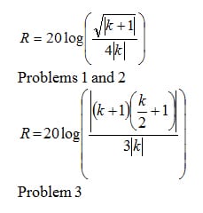
The Reflection Term R depends on the shape of the shield and the source, for problem 1, 2, and 3 Schelunkoff obtained the following expressions:
Where k is the intrinsic impedance ratio of the shield Zi to the wave impedance Zw. The magnitude of |k| = |Zi/Zw| is a measure of the change in the field as it enters or leaves the barrier. Large values >> 1 or small values << 1 indicates large impedance mismatch at the surface of the barrier and results in large values of reflection.
For E-Fields k has the following relationship:
For H fields k has the following relation:
For practical shields |k| << 1 equations (4) and (5) reduce to:
The reflection term for all three problems may be rewritten as:
where: c = 4 for problems one and two, plane and cylindrical waves; and c = 3 for problem three for spheres.
This approach is used by many practicing engineers, however the basic problem with using these equations is the fact the equations are based on planer waves which exist in the far field where the wave impedance is consider to be that of free space, ≈ 377 ohms. When performing shielding effectiveness measurements the practicing engineer must understand the relationship of near and far conditions when specifying shielding material or attempting to measure the susceptibility of sensitive electronic equipment. This holds true more so when attempting to shield a piece of equipment from an outside threat, e.g. safety of flight systems of aircraft and or safety controls of a nuclear process ageist cell phones and other similar wireless devices.
Understanding Near Field and Far Field Relationship
More often than not shielding material measurements are made in the near field where the wave impedance is not equal to 377 ohms and the general axiom of SE = SE(H) = SE(E) does not hold up, and/or the measurements are performed within a uniform field, (Planer Wave Characteristics) by using coaxial test fixtures and or TEM cells. These test methods work well for very high frequencies where the material may be located in the far field. However, once the low frequency shielding effectiveness measurement is attempted to be made, it will more than likely be in the near field and would be impossible to determine the true shielding effectiveness of the material as it will exhibit one shielding effectiveness value for the electric field and a different one for the magnetic field. Al of this is dependent on the distance of the shielding material in relation to the source.
When the shielding material is close to the source the wave impedance is a function of the source properties. The wave impedance is the ratio of the electric and magnetic fields where:
If the source that is being shielded ageist is a high current source with low voltage the predominate field will be magnetic, and if the source has a high voltage characteristic with low current the predominant field will exhibit the characteristics of an electric field.
Figure 1 below illustrates the basic impedance transition region and where which theories hold up and the associated test and typical measurement approach that is used.

The only way to obtain a meaningful shielding effectiveness measurement in the near field is to have the threat source nearby, and then measuring the power density with special probes or smart sensors and computing the shielding effectiveness with and without the actual threat source.
Measurements to Illustrate Differences in the Near and Far Field Shielding Effectiveness
To illustrate the principles in Figure 1 testing was performed by using three methods: Modified Method of MIL-STD-83528 at 0.5 m using loops and rods with reference antennas, BiconLogPeriodic antenna at 3 meters, and the use uniform fields generated within a Crawford Cell.. Figure 2 below shows the basic test setup of MIL-DTL-23528 performed at 0.5 m. The material being evaluated is aluminized plastic which is thin enough to provide measurable values of shielding effectiveness.
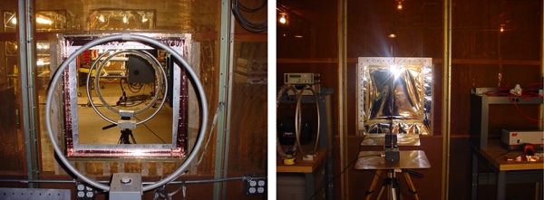
The testing was done at 0.5 m in accordance with MIL-DTL-23528 and illustrates the concept of near field measurements where SE does not equal to SE(H) = SE(E) and the lab measurements supporting this concept is seen in Figure 3 below. One of the main differences besides the change in distance is the use of reference antennas of like build at 0.5 meters from the source. As an example, if the source antenna was a rod, (electric field) it would have a matched reference rod at 0.5 meters from it on the other side. For inside the enclosure an active rod or loop antenna would be used depending on either measuring the electric or magnetic field.
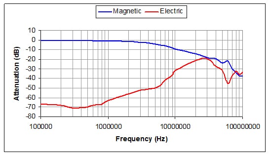
Notice in Figure 4 how the graphed data follows the trend of wave impedance as it changes in accordance to wavelength as seen in Figure1, – showing a transition from near field to far field where the magnetic and electric field shielding effectiveness are almost the same.
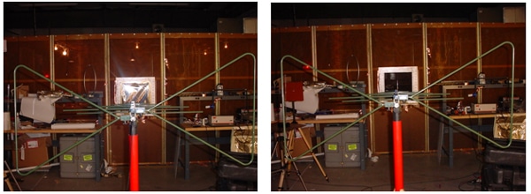
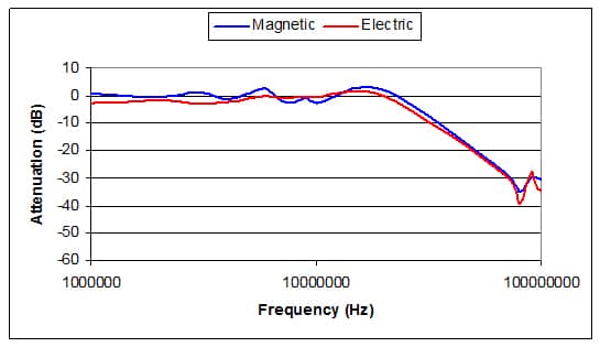
In order to illustrate the concept of far field measurements and that Schelkunoff’s equations are applicable for plane waves, a BiconLogPerodic antenna, (BLPA) at three meters was used as the source. Measurements inside the enclosure were performed with a loop or rod antenna respectively at 30 cm. Refer to Figure 7 below. As seen in the measurements below in Figure 8 the electric field shielding effectiveness is within 3 dB of that of the magnetic field shielding effectiveness as predicted by Schelkunoff’s shielding theory and that electromagnetic waves are planer at this distance.
Figure 4 below shows the BLPA method at 3 meters. The frequency starts at 1 MHz to ensure the measurements are performed within the far field region.
As can been seen in Figure 5 below the measurements of the shielding effectiveness are for the electric field and the magnetic field are relatively the same.
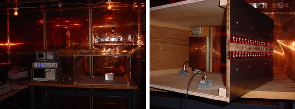
Next a final measurement was performed using a Crawford Cell which would produce a uniform plane wave from 100 kHz to 100 MHz to fill the gap in the BLPA measurement. A Bdot sensor and fractional dipole was used as a reference and measurement sensors for the test. Figure 6 shows the basic test setup and the Crawford Cell being measured for a uniform field generation. A small shielded box with a six inch square test window was used to hold the material under test. A sense probe was located inside the box while the reference probe measured the field being generated between the plates.
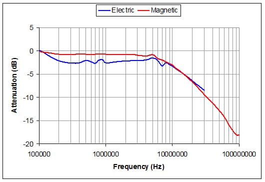
As expected the test results were similar to that of the BLPA in the far field. As may be seen once again, when using plane waves, Schelkunoff’s equations are valid, and only valid for plane waves. The data in Figure 7 shows that the shielding effectiveness for the electric field and magnetic field are within 3 dB of each other. And at 100 kHz there is no shielding of the electric and magnetic fields by the aluminized plastic.
CONCLUSIONS
When the shielding effectiveness of the aluminized plastic is compared to the far field and the near field measurements using antenna techniques it is clear that the wave impedance conditions affect the outcome. However when we treat the shielding effectiveness measurement with a uniform field such that used in the standard shielding effectives equations, the results are similar for both types of fields illustrating that these conditions do not reflect the real world shielding effectiveness. The practicing engineer must understand these differences and develop meaning tests which considers the threat source and the relative differences in defining meaningful shielding effectiveness values.
Finally, the only shielding effectiveness measurement that can be relied on for near field values are the ones which consider power densities which treat the magnetic and electric field separately first, and then combines them in a single calculation of power.
For more information on shielding, visit our shielding channel here.
ABOUT THE AUTHORS
Kermit O. Phipps is a NARTE-certified EMC engineer and conducts tests and evaluations of equipment performance in accordance with standards of ANSI/IEEE, IEC, U.S. military and UL, as wel as with the EPRI system compatibility test protocols for EPRI. He served in the U.S. Air Force as a manual electronic warfare and component specialist, resolving hardware and software problems. He conducts research on surge protection, powerline filters, shielding effectiveness and electromagnetic interference. Mr. Phipps is the author and co-author of test plans, protocols and research papers presented at international power quality and EMC conferences. He has conducted a number of power quality and EMC conferences, training sessions and field investigations. Most recently, he completed voluntary work as chairman in developing a new EMC standard for powerline filters, IEEE 1560.
Philip F. Keebler has conducted system compatibility research on personal computers, lighting, medical equipment and Internet data center equipment. The lighting tasks were associated with characterizing electronic fluorescent and magnetic HID ballasts, electronic fluorescent and HID ballast interference, electronic fluorescent and HIS ballasts failures, electronic fluorescent and HID lamp failures. He has drafted test protocols and performance criteria for SCRP tasks relating to PQ and EMC. Mr. Keebler also manages the EMC group at EPRI, where EMC site surveys are conducted, end-use devices are tested for EMC, EMC audits are conducted and solutions to EMI problems are identified. He has compelted his service as editor developing a new EMC standard for power-line filters, IEEE 1560.


