Introduction
Lightning may produce a spectacular display when viewed, but the associated electromagnetic effects (EME) has the potential (pun intended) to severely damage electrical and electronic circuits. MIL-STD-461G added a new test method to evaluate device tolerance for induced current on equipment cables or insulation breakdown from the effects of indirect lightning. Although new to MIL-STD-461, the induced lightning tests have a background in civil aviation with similar test methods documented in RTCA/DO-160.
Most equipment has been evaluated for effects from indirect lightning events using CS115 and CS116 test methods for several years and these test methods remain present in revision “G” for qualifying equipment. The CS117 test method addition primarily targets aircraft flight or safety critical equipment and some other critical applications calling for this evaluation.
Note that the CS117 test method does not provide test coverage for MIL-STD-464 lightning direct effects or nearby lightning requirements.
Planning for Test
Is testing applicable to my device?
MIL-STD-461G, Table V lists CS117 as having Limited (L) applicability or Specified (S) in procurement contract documents. The Limited applicability defers to as specified in individual section of the standard. The individual section (5.15) lists applicability as safety-critical equipment and applies testing to the interconnecting cables including power cables and individual high side power leads. Additionally, non-safety critical equipment that are part of or connected to safety-critical are considered as applicable for this test method. Normally a procurement contract will specify test applicability but consider the design implications if developing a product that potentially fits into the critical category.
What waveforms and test levels apply?
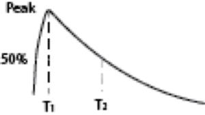
Waveforms associated with CS117 are classified as double exponential or damped sine wave where the waveform generator provides control of the rise and decay times of various waveforms. Figure 1 provides a generic waveform shape. The double exponential waveform on the left has an amplitude in current (I) terms or in voltage (V) terms. T1 denote the rise time and T2 denotes the decay time to 50% of the peak. The rise and decay times vary depending on the waveform selected for test with the detailed waveform parameters provided in the standard. The waveform parameters are verified by applying the transient to a calibration loop configured as a short circuit for current (I) waveforms and configured as an open circuit for voltage (V) waveforms.
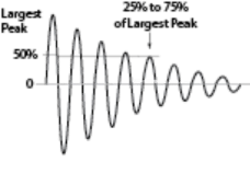
The damped sine or cosine waveform on the right amplitude is in voltage terms and has a frequency of 1 MHz or 10 MHz with both frequencies used for testing. The dampening factor is not specified but based on the waveform drawing, the 50% (±25%) decay is reached by the 5th cycle.


Figure 1: Double Exponential (left) and Damped Sine (right) Waveforms
What is a calibration loop?
A low impedance wire loop. Note that impedance is the basis so low self-inductance and low resistance must be considered. High current levels are associated so the wire should be large enough to prevent potential I2R heating issues. The loop passes through the injection transformer in a single turn with enough length to support injection transformer and monitor probe placement.
What is implied by test level versus limit level?
The test level is the target amplitude for the specific waveform. The waveform calibration verifies that the test level can be produced into the short circuit calibration loop for double-exponential current waveforms or open calibration loop for damped sine voltage waveforms. During test the characteristic cable impedance is not known, so adjusting the amplitude to achieve the test level we may encounter an inability to attain the specified current or voltage. In this case the limit level is used to prevent over-stressing the circuit. We must realize that cable placement can affect the impedance so maintain the test configuration to help with standardization.
Table VII in MIL-STD-461G lists the applicable waveforms and test/limit levels for multiple stroke and multiple burst testing. Single stroke tests are not separately specified but combined into the multiple stroke tests by elevating the first stroke test/limit levels.
The table also sets the test/limit levels for internal and external installation applications. Table VII provides the generic test/limit levels, however if platform data is available the test/limit level should be tailored to use platform specific information.
What are low count wire bundles?
Table VII includes a separate test/limit level for individual power leads or low count wire bundles. The lesser of the individual lead test/limit current multiplied by the number of wires or the specified test/limit level is used. Depending on the waveform and test level, a bundle with as many as 10-wires could be considered as a low count cable. For example, in Table VII 1st row (see Figure 2), the internal first stroke individual Iτ is 60 A and bundle Iτ is 600 A so a 9-wire bundle would use an Iτ of 540 A. If this test level was set, then subsequent strokes would apply 270 A, exceeding the test level prescribed. This issue should be addressed in the test procedure to avoid confusion about the test execution and acceptance of the product.

The standard treats a wire bundle as all wires associated with an interface connector. I somewhat disagree with this standardization when dealing with cable injection testing including the CS117 test method. We need to understand the installation cable layout to determine test levels. Consider that a single interface may have wiring that routes two different directions upon exiting the device – e.g., some wires route to the cockpit control head and other wires route to sensors in the aircraft tail. Coupling exposure is not equal so a common mode current could become differential at the device creating an interference that is not apparent if common mode. A test procedure should address this potential risk and establish appropriate testing.
What about waveform 6 applicability?
MIL-STD-461G, Table VII under the multiple burst heading a discussion regarding waveform 6 with some ambiguity. “Equipment installations that utilize short, low impedance cable bundle installations.” “Short” and “low” lack definition so the test procedure needs to document applicability with the criteria used to determine applicability. Some would consider less that 1-meter as short and others may consider less than 20-meters as short – this decision needs to be agreed upon prior to testing instead of obtaining a report rejection.
Waveform Calibration
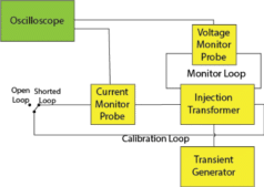
Waveform calibration is an integral part of the CS117 test method as with most test methods in MIL-STD-461G under the signal integrity check mantra. The calibration process confirms the ability for the test level to be attained with the test waveform parameters using the calibration loop configured as shorted loop or open loop as applicable for the test level waveform. Referring to Figure 2, you can see that waveform 1 is associated with the test current (not the voltage limit waveform 2) so the shorted loop configuration would be appropriate for the calibration.
Establish the calibration configuration (see Figure 3) with a shorted calibration loop for calibration of the current waveform. Adjust the transient generator settings to the Iτ level applicable to the cable to be tested and record the settings and waveform. Verify that the waveform parameters comply with the timing parameters established for that waveform.
It is not necessary for the transient generator to produce the associated VL limit waveform, however if the transient generator can produce the VL level in the shorted loop configuration the settings and waveforms should be recorded.
Accomplish the calibration process for each applicable waveform recording the settings and waveform parameters. For multiple stroke and multiple burst tests, verify the pulse patterns and timing.
Reverse the transient generator polarity and repeat the calibration process.

Figure 3: Calibration Configuration
EUT Testing
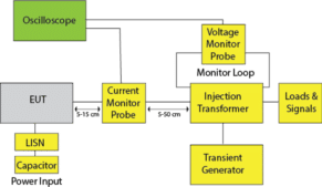
Now that the waveform calibration has been successfully completed, the test configuration can be established and testing can proceed. Figure 4 shows the basic test configuration for signal or control lines. For power line tests, the injection transformer would be installed between the LISNs and the EUT and recall that MIL-STD-461 specifies that the power cable be unshielded and have a length of 2.5-meters for testing.
Once configured, establish EUT operation and allow the EUT to stabilize. Start applying transients with the transient generator adjusted to zero then increase the transient generator amplitude settings or injection transformer configuration until the test level or the limit level is attained. Note that if injection transformer configuration is changed a re-calibration is required. As the amplitude is increased monitor the EUT performance for susceptibility indications.
- If susceptibility is NOT observed the EUT is considered compliant.
- If susceptibility outside the performance requirements is observed the EUT is considered non-compliant.
- If the limit level is attained before the test level is reached an evaluation is used to determine acceptability using the following criteria:
- If the transient generator produced a compliant limit level waveform during calibration, the test is acceptable.
- If the specified limit level waveform is attained during test and the waveshape meets the parameters, the test is acceptable.
- If one of the above criteria is not met, a retest is required using a transient generator that can meet the limit level waveform requirements.
Multiple stroke testing applies at least ten multiple strokes while monitoring EUT performance. The time between multiple stroke applications shall not exceed 5-minutes.
Multiple burst testing applies a multiple burst every 3-seconds for at least 5-minutes while monitoring the EUT for susceptibility indications.
Remember that the testing is repeated with the transient generator polarity reversed.

Figure 4: Test Configuration
Note that the standard provides significant guidance on measuring the applied waveforms dealing with RF noise on the waveform. Since the standard is thorough on this topic, I am not going to repeat that information in this article. The guidance is in the MIL-STD-461G appendix.
Remember that cable placement during test may influence the waveform and provide alternate current paths from parasitic reactance – note the physical parameters and conform to the standard layout – good photos of the configuration provides the ability to repeat the test with minimum variance.
Summary
As we have discussed, planning for this test is essential and that planning includes understanding the installation and platform construction. Understanding the application and test requirements is needed to support inclusion of control measures to prevent susceptibility.
Pay close attention in selecting acceptance criteria for device performance. Failing to allow minor perturbations that do not impair the critical performance can affect the product design and associated costs.
Don’t forget that the CS117 testing involves some relatively high current and voltage levels. Maintain a safe test environment to prevent shocking events that can result in injury. Use appropriate personal protective equipment in case the EUT should experience rapid disassembly from high level transients.
The overall test program for CS117 requires many measurement system details so pay attention to the testing.


