Stephan Braun, Arnd Frech
GAUSS INSTRUMENTS GmbH, Munich, Germany
I. INTRODUCTION
With the expansion of the generic standard CISPR 16-1-1 to include spectrum analyzers and the “FFT-based measuring instrument”, the floodgates have been opened for a change in technology. The use of the spectrum analyzer for EMC measurements was included into the generic standard to be able to measure primary stationary EMC emissions, such as those emitted by a PC, both cost-effectively and quickly. The FFT-based measuring instrument, on the other hand, was placed into the standard to be able to analyze and measure complex interference sources with greater reliability and higher speed. By digitalizing the measuring equipment, different processes are now available for the implementation of a test receiver. First, there are classical test receivers that mix down to a narrow band, are tuned, and then carry out the measurement at one frequency point at a time. There are also baseband measuring units equipped with very powerful gigasample A/D converters and FPGAs which carry out the measurement itself, that is emulating a test receiver or spectrum analyzer, in a fully digital manner at several thousand frequency points. As a bridge technology, there are still test receivers with a broader intermediate frequency, typically about 25 MHZ, which carry out the evaluation over this bandwidth, measuring individual bands sequentially and composing them into a spectrum.
However, CISPR 16-1-1 has strict requirements for such measuring units with respect to the dynamics for broadband interference. The central challenge is to provide the dynamics for pulses in Band C with a low pulse repetition rate and a quasi-peak value evaluation. To achieve these dynamics, different concepts are used. For broadband measurement systems, multistage A/D converter systems are used to improve the dynamics. For test receivers, this is achieved using preselection.
This article gives an overview of the requirements for measurement equipment with respect to the extended CISPR 16-1-1 standard. It discusses the challenges, approaches, and possible limitations. Newer procedures such as Noise Floor Extension (NFE) are also discussed with respect to opportunities and risks.
II. RADIO INTERFERENCE TEST RECEIVERS AND SPECTRUM ANALYZERS
Radio interference test receivers measure the emission signal in the frequency range. The measurement takes place sequentially at several thousand frequency points. Superheterodyne receivers have been widely used until now. A block diagram of a conventional superheterodyne receiver is shown in Figure 1.

Fig. 1. Conventional superheterodyne receiver
A preselection suppresses signals outside the band in which the measurements are being carried out. This increases the dynamics in comparison with spectrum analyzers, particularly for broadband interference.
A mixer and an interference oscillator perform a frequency conversion to an intermediate frequency. The signal is bandpass filtered through the intermediate frequency filter. The intermediate frequency filter must comply with the selectivity specified in CISPR 16-1-1. The output signal is weighted using a peak value, quasi-peak value, mean value, CISPR-AVG, CISPR-AVG-RMS detector. The intermediate frequency signal is generally provided in analog as well. Spectrum analyzers can carry out a swept scan and use a video filter to calculate the average. Here, we speak of calculating the logarithmic mean.
III. EMC-TIME DOMAIN MEASUREMENT SYSTEM
In the EMC time domain measurement system, the input signal is sampled and digitized using an analog-digital converter unit for measurement in the frequency range 9 kHz – 1 GHz. For measurements above 1 GHz, there is a broadband frequency conversion. The spectral calculation is done using short-time FFT. A block diagram of an EMC time domain measurement system is shown in Figure 2.

Fig. 2. EMC time domain measurement system
For radiated emission measurements, one typically uses a broadband logarithmic-periodic antenna. Alternatively, measurements can be carried out using absorber clamps or network replication. To examine coupling to antennas in the vehicle, the EMC time domain measurement system can be connected directly. The input signal is digitalized using a multistage analog-digital converter. The multistage analog-digital converter system performs the digitalization to a floating point number [1]. This permits it to achieve an equivalent dynamic range of about 20 bits. This permits a high sensitivity of about −20 dBµV (Band B) to be achieved while simultaneously recording pulses of several volts. Using powerful FPGAs with a computational power corresponding to about 20 standard PCs, the evaluation over a bandwidth of 162.5 MHz takes place entirely without any gaps in real time. Such an EMC time domain measurement system was described for the first time in [2]. It permitted measurement to be accelerated by a factor of 1000.
A. Short-time FFT
The short-time FFT is an FFT computation over a limited segment that is offset in time. Using short-time FFT, a spectrogram can be calculated that corresponds to a representation of the spectrum over time. While stationary signals have a constant spectrum over time, the spectrogram shows the instationary behavior of the interference signal. The mathematical definition of the short-time FFT is given by:
Since the window function w[n] is symmetrical, there are multiple options for converting Eq. 1. For the real calculation, the conversion takes place in such a way that the window function is not shifted, but rather the input signal. Additional simplifications are possible, in particular for the application of interference emission testing, since the phase is not evaluated further in that case. w[n] is the window function modeled by the intermediate frequency filter of a test receiver [3].
B. Comparison with a conventional test receiver
The literature states that the short-time FFT is equivalent to an arrangement of baseband mixers and a filter bank [4],[5]. The short-time FFT can also be derived from an arrangement of a filter bank [6]. A block diagram of such an arrangement is shown in Figure 3.

Fig. 3. Filter bank
The behavior of the decimator is given by:
where fs is the sampling rate of the analog-digital converter and fsbb is the inverse step size of the short-time FFT which corresponds to the baseband sampling frequency. W [f ] is the discretized transmission function. The baseband sampling frequency fsbb must be sufficiently large for the Nyquist requirement to be met, for example in the digital implementation of the quasi-peak value detector. Too low a sampling rate leads to measurement errors in transient signals.
C. Measurements above the Nyquist frequency
Typically, the sampling rate of available analog-digital converters is an order of magnitude lower than the available frequency ranges of mixers. A combination of a very broadband conversion unit [7] which mixes the frequency range up to 40 GHz into the range below 1 GHz is used to permit measurements above the Nyquist frequency.
D. Preselection
Time domain measurement systems also have preselection with a bandwidth of 300 MHz. This improves the dynamics even beyond the multistage A/D converter system. Preselection is located before the multistage A/D converter system with the integrated 20 dB preamplifier.
IV. TEST RECEIVER WITH BROADBAND INTERMEDIATE FREQUENCY
In addition to the very broadband time domain measurement systems, there are also frequency conversion measurement equipment items that use a broadband intermediate frequency, digitalize the intermediate frequency signal using an A/D converter, and carry out the calculation of the short-time FFT in segments of at most 25 MHz.
V. REQUIREMENTS OF THE CISPR 16-1-1 STANDARD
CISPR 16-1-1 [8] requires a particular display behavior in an instrument for different test signals. It draws a distinction between:
• Display behaviors for sine waves and pulse sequences
• Requirements for dynamics
• Requirements for inputs and outputs
A. Display behavior for sine waves and pulse sequences
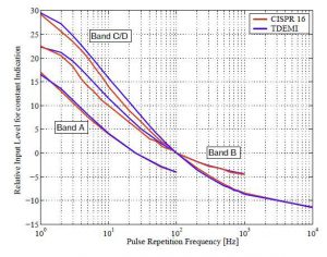
A CISPR 16-1-1-compliant instrument must have a sinusoidal accuracy of +/-2 dB. Depending on the detector, it must also reach a certain relative display value for a sinusoidal signal. Furthermore, the evaluation curves required by a change in the display with respect to the pulse repetition rate must also be observed. An example for the A, B, C, and D bands is shown in Figure 4. The deviations are significantly lower than the permitted tolerances.

Fig. 4. Evaluation curves according to CISPR requirement
B. Requirements for dynamics
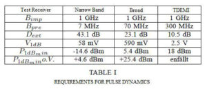
The same requirements for dynamics apply to all measurement devices. For the restricted use of the spectrum analyzer, there are some simplifications provided. For test receivers and test receivers with broad intermediate frequencies, the dynamics are determined by the 1 dB compression point of the system. Furthermore, for pulses the dynamics are primarily determined by the bandwidth of the preselection. In baseband systems, the dynamics for sinusoidal signals are determined with the control range of the first A/D converter and the dynamics for broadband pulses by the entire control range of the floating-point A/D converter system. In the following, we want to present the requirements for the dynamics at a general level first, then for concrete examples. In this, we will use the requirements of Band C pursuant to CISPR 16-1-1. Usually, the test receivers with activated preamplifers of 20 dB have a noise floor of about -7 dBuV when evaluating with the mean value detector. For quasi-peaks, this results in a noise floor of 0 dBuV.
The reference for display of the quasi-peak value detector is 100 Hz. Here, the display value must be 31.5 dB higher than for a single current pulse. In reverse, this means that the signal current pulse must have a sufficient distance above the noise floor. To prevent excessive noise, there should be at least a signal/noise distance of 10 dB. Furthermore, there must also be a dynamic reserve in the amount of the steps of the attenuator. Without the dynamic reserve, this results in a requirement that the test receiver with activated preamplifier must be able to display at least pulses with a display level of 41.5 dBuV in Band C correctly and with 0 dB attenuation. A CISPR 16-1-1-compliant pulse generator that generates a display of 60 dBuV on test receivers at 100 Hz has a pulse area of 0.044 uVs, a pulse width of 300 ps, and therefore a pulse voltage of 146 V. This results in a pulse voltage for the display of 41.5 dBuV of about 8.4 V. A complete broadband measurement unit without any preselection would therefore have to have a 1 dB compression point of 28.5 dBm. The use of preselection reduces this requirement. Here, the dynamic requirement is reduced according to the formula:
In the following, the requirements for a traditional test receiver with a narrow preselection, a test receiver with a broad intermediate frequency and broad preselection, and the time domain measurement system which works on a broadband basis are all illustrated for Band C.

The preselection in narrow-band test receivers reduces requirements by about 43 dB, so at the input of the preamplifier, a requirement for the 1 dB compression point of -14.6 dBm, or 92.4 dBuV results. At the mixer, generally 4.6 dBm. This does not represent any great challenge for the test device. The technical challenge in these test devices is in implementing preselection. In test receivers with broad intermediate frequencies, there are significantly stricter requirements, some of which can no longer be met by the measurement units However, this type of measurement units can also be with a relief of about 15 dB according to CISPR 16-1-1 2010 for certain measurements. Measurement equipment capable of providing a 1 dB compression point of about 25 dBm with the preamplifier turned off can be used for full compliance measurements. If necessary, the dynamics can be improved with processes like Noise Floor Extension or digital correction. However, this type of process can lead to differences in real tests and thus to mismeasurement.
For broadband time domain measurement units, the challenge is to achieve very high dynamics with preamplifiers of 18 dBm on the input. This requirement is achieved using a power splitter and a multichannel A/D converter system. There are strict requirements for linearity. Typically, these measurement units have a control range of up to about 5 V. This leaves dynamic reserves of about 6 dB.
C. Requirements for the dynamics of spectrum analyzers
Spectrum analyzers generally have a preselection that is only used to suppress undesired mixing products. In contrast with the test receiver, this was not primarily developed to increase dynamics. However, high-quality spectrum analyzers have a high 1 dB compression point of about 13 dBm. The standard CISPR 16-1-1 Ed 2010 took this situation into consideration and permitted the use of spectrum analyzers for test objects whose pulse repetition rate is high enough that the dynamics of the spectrum analyzer are sufficient. Test objects with a pulse repetition rate greater than 20 Hz may be measured. At the same time, the dynamics of the spectrum analyzer must comply with CISPR 16-1-1 for pulse repetition rates of over 20 Hz. This corresponds to a relief of about 23 dB. Spectrum analyzers with high performance provide sufficient dynamics here. However, it should be noted that this is generally not noted in the data sheet and must therefore be evaluated by the user personally.
VI. MEASUREMENTS
A. Pulse dynamics for classical test receivers
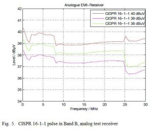
Measurements were carried out that demonstrate the limits of the pulse dynamics of classical test receivers. For example, a classical test receiver was exposed in Band B to the CISPR 16-1-1 pulse. The level varied over the range 39 dBuV to 41 dBuV. Figure 5 shows the measurement results. Ideally, the pulse spectrum shown is flat, and all spectra should be parallel at the levels of 38, 39, and 40 dBuV. However, it turns out that in the different frequency ranges of preselection, the linearity and the autorange of the analog test receiver behave differently. In the upper frequency range, the 1 dB compression point of the test receiver is lower than in the middle range, leading to a low display value. Starting at 40 dBuV, the input attenuator switches to 5 dB. This drives the upper frequency range out of compression and the display clearly approaches the actual level. It is clear that for this analog test receiver, the tolerances of CISPR 16-1-1 are fully exhausted.

B. Dynamics of the time domain measurement system
A time domain measurement system was used for examination. Here, a pulse sequence according to the CISPR 16-1-1 standard was applied to the device and the real-time spectrogram, evaluated with the peak-value detector, was displayed. The result of the measurement is shown in Figure 6. The result is displayed in three dimensions as a spectrogram. It is clear to see that each pulse is correctly measured and displayed. Dynamics are over 55 dB, although CISPR 16-1-1 requires only 43.5 dB. The display accuracy corresponds to the requirements of CISPR 16-1-1.
C. Extending the dynamic range with Noise Floor Extension
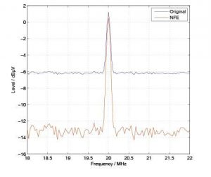
Noise Floor Extension (NFE) is a method that permits the noise floor to be lowered. During noise floor lowering, the noise of the measurement unit is subtracted from the measurement result after intermediate frequency filtering and detector evaluation. Since noise is a statistical process, this leads to influences on the level accuracy in the vicinity of the noise floor. In the following, an NFE of 8 dB is generated.

Fig. 6. Spectrogram representation of a sequence of pulses

Fig. 7. Application of Noise Floor Extension
Figure 7 shows the result of the real spectrum as well as the corrected spectrum with NFE. For the sinusoidal signal, the dynamic range is improved by about 8 dB. However, it is also clear to see that the noise floor has a significantly higher variance. This variance leads to measurement uncertainties that must be taken into consideration.
VII. SUMMARY
This article discussed the requirements for analog test receivers, test receivers with broad intermediate frequency, and FFT-based test receivers specified by the CISPR 16-1-1 standard. It was shown that analog test receivers provide sufficient dynamics for emission measurements. Effects due to compression of the mixer and autorange were discussed. Furthermore, advantages and disadvantages of the Noise Floor Extension process were discussed. The requirements for dynamics were discussed for test receivers with broadband intermediate frequencies. These represent a significant challenge for the 1 dB compression point, which is generally not reached. This type of test receiver, however, can be used if the easements of about 20 dB for use as a spectrum analyzer are utilized. Moreover, there are broadband measurement systems with multistage A/D converters and preselection that comply with the dynamic requirements of CISPR 16-1-1.
REFERENCES
[1] S. Braun and P. Russer, “A Low-Noise Multiresolution High-Dynamic Ultra-Broad-Band Time-Domain EMI Measurement System,” IEEE Transactions on Microwave Theory and Techniques, vol. 53, pp. 3354–3363, Nov 2005.
[2] S. Braun, M. Al-Qedra, and P. Russer, “A novel realtime time-domain emi measurement system based on field programmable gate arrays,” in 17th International Zurich Symposium on Electromagnetic Compatibility, Digest, (Singapore), pp. 501–504, Feb. 2006.
[3] S. Braun, F. Krug, and P. Russer, “A novel automatic digital quasi-peak detector for a time domain measurement system,” in 2004 IEEE International Symposium On Electromagnetic Compatibility Digest, August 9–14, Santa Clara, USA, vol. 3, pp. 919–924, Aug. 2004.
[4] V. Oppenheim and R. W. Schafer, Discrete–Time Signal Processing. ISBN0-13-214107-8, Prentice-Hall, 1999.
[5] F. J. Harris, “On the Use of Windows for Harmonic Analysis with the Discrete Fourier Transform,” in Proceeding of the IEEE, vol. 66, no. 1, pp. 51–83, 1978.
[6] J. Allen and L. Rabiner, “A unified approach to short-time Fourier analysis and synthesis,” in Proceedings of the IEEE, vol. 65, pp. 1558–1564, 1977.
[7] C. Hoffmann, S. Braun, and P. Russer, “A Broadband Time-Domain EMI Measurement System up to 18 GHz,” in In EMC Europe 2010, Breslau, Polen, September 2010, pp. –, September 2010.
[8] CISPR16-1-1 Ed. 3, Specification for radio disturbance and immunity measuring apparatus and methods Part 1-1: Radio disturbance and immunity measuring apparatus – Measuring apparatus. International Electrotechnical Commission, 2010.


