Pat Moore, MILMEGA Ltd., UK
Introduction
With the recent release of IEC61000-4-3 Edition 3, many EMC test houses are actively researching the availability of equipment capable of meeting the testing demands presented by the new 6 GHz upper frequency limit. The conventional solution offered by EMC equipment suppliers has several major disadvantages, particularly as regards frequency and power overkill. This article details the design rationale and the application of an alternative approach that recognizes and leverages on the favorable attributes of a horn antenna’s gain / frequency characteristic.
Conventional Approach
In an ideal world the conventional approach would offer a single amplifier / single antenna combination covering the old and new bands (all the way from 80MHz to 6GHz), with the characteristics of the combination matching the needs of the test system.
A single amplifier / antenna solution is not feasible, so inevitably the offering from test equipment suppliers is a multi-amplifier / multi-antenna one. As regards powering the new 1-6GHz band, the most usual offering includes a 1-4GHz solid-state amplifier, followed by either a 4-8GHz TWT amplifier or a 4-10GHz solid-state amplifier.
The antenna proposal usually involves replacing the existing antenna with an ultra-broadband antenna covering the old (80MHz – 1GHz) part of the test band and the first 4GHz of the new band. A second antenna then covers the remainder of the new band from 4GHz to 6GHz. Mainly due to a poor choice of where the 1-6GHz band is split between the antennas, this non-ideal conventional approach has several weaknesses.
This can best be explained pictorially.

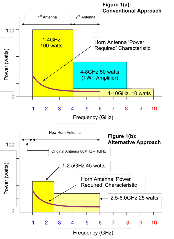
Figure 1(a) shows the power amplifier / antenna options usually offered for a test field strength of 10 v/m @ 3m. The 1st antenna covers 80MHz to 4GHz. Two amplifiers power this new antenna. The first amplifier (not depicted) provides the power from 80MHz to 1GHz, The second amplifier (shown) provides the power from 1-4GHz. An unfortunate drawback in using the ultra-broadband antenna is that unusually high amounts of power are required above 1 GHz. This is a severe side-effect in that a horn microwave antenna1 needs only a fraction of this power, and no advantage is taken of the favorable drop in required-input-power that exists with the microwave horn antenna (mauve curve: this curve represents the power required at the antenna connector to produce a test field of 10 v/m @3 meters with amplitude modulation on plus 3dB for field variation).
The 4-8GHz TWT amplifier is wasteful in both frequency and power. Only half the amplifier’s frequency band is used, and the power level has significant overkill built in to compensate for the TWT amplifier’s poor linearity, and it’s inability to withstand large amounts of reflected power. Note that a TWT amplifier has to be operated at less than half-power to be within its linear range, and at about a quarter-power to cope with a severe mismatches. Also note that even with the TWT amplifier operating in a backed-off condition, a second unwanted test signal of non-trivial power is produced at the first harmonic frequency.
Finally, offered as an alternative to the TWT amplifier is a 4-10GHz solid-state amplifier, also intended to cover the remaining 4-6GHz of the new band. This is a closer match power-wise to the system design requirements, but as can be seen, presents a serious frequency overkill situation in that two thirds of it’s band is not required by the test system.
Alternative Approach
Figure 1(b) shows an alternative approach based on the observation that the horn antenna input-power-requirement characteristic drops fairly sharply over 1-2.5GHz, and then more modestly over 2.5-6GHz, making 2.5GHz a sensible band-break point.
The existing 80MHz -1GHz antenna is retained and a single microwave horn antenna is introduced to cover the new 1-6 GHz band in its entirety. Assuming it has enough power overhead to meet the new linearity requirements outlined in Edition 3, the original power amplifier still powers the original antenna. Otherwise the amplifier is replaced with a suitable higher power version. Two solid-state amplifiers covering 1-6GHz of appropriate power levels power the horn antenna.
As can be seen in the figure, this approach is an exact fit frequency-wise, and more closely follows the antenna requirements for input power. With this alternative approach in mind, MILMEGA has introduced a family of solid-state dual-band internally-switched amplifiers specifically designed to match the new test system criteria.
Dual-Band Amplifier
Based on it’s corporate structure amplifier (CSA) topology, and with all the advantages this design methodology affords2, MILMEGA has developed a suite of solid-state amplifiers that provide higher power over the 1-2.5GHz segment of the new test band, and lower power over the remaining 2.5-6GHz. Figure 2 shows the available power profiles. Unlike the conventional approach where separate amplifiers require external switch boxes, internal switching permits very short internal cable runs between switches which equates to almost zero losses. The amplifier can be controlled and monitored remotely and most importantly for the application, provides 100% forward power into any load.

Practicalities of Integration
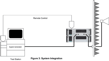
Figure 3 shows the dual-band amplifier integrated into the system configured for 1-6GHz testing. The power profile selected obviously depends upon the volts per meter required and the losses of the particular system at hand.
Of particular importance is cable loss between the power amplifier and the antenna. Cable loss is minimized to retain as much of the system power budget as possible, and hence maintain the design margin (i.e. the allowance for system-losses plus a generous contingency). Also, and very importantly, the frequency characteristic of the cable (loss increases with frequency) is opposite to that of the microwave horn antenna, and an excessively long interconnecting cable, besides being wasteful of RF power, would tend to nullify the tremendous advantage that the horn antenna input-power characteristic presents.

As should be the case with any power amplifier integration, the output cable to the antenna should be high grade and as short as is physically possible. This is shown in the figure where the dual-band amplifier is located close to the chamber wall next to the RF bulkhead connector. Of help here is the fact that the single RF input / output feature means no extra external cable runs are required.
Every effort should be made to minimize the length of cable from the bulkhead connector to the horn antenna. The horn antenna dimensions are small, allowing the antenna to be located comparatively close to the chamber wall. Interaction with the chamber wall depends on the direction and strength of any backlobes. These should be trivial, and hence a non-issue, but it is good practice to obtain backlobe data from the manufacturer to allow a sensible minimum separation distance can be ascertained.
Losses in the cable connecting the signal generator to the input of the amplifier are less critical since simply increasing the power from the signal generator compensates for these. This means the signal generator can be placed in it’s regular position at the test-operator station. However, it is still good design practice to maintain as much of the signal generator power overhead as possible, so the cable should not be unnecessarily long. The length of the remote control cable is also not critical as long as the stated maximum circuit length is not exceeded.
The dual-band amplifier remote control options include IEEE488/RS232 and Ethernet / USB (Plug and Play). These can be used by the system software to switch bands (a matter of milliseconds) and monitor vital health signs such as forward and reverse power levels.
The next level in integration would be to arrange switching between the old and new hardware such that the software conducts the low frequency and new high frequency tests successively and seamlessly, without the need for test operator intervention. This would require external switching between the original low frequency amplifier and the new dual band amplifier, and external switching between the lower frequency and microwave antennas.
In this case, to minimize cable losses, the high-power RF switching (amplifiers and antennas) should again take place close to the RF bulkhead connector, and all switching cable runs should again be as short as is practically possible. The low-loss switching advantage of the dual band amplifier ripples through to this next level of integration.
Conclusion
The conventional approach to providing test fields for the IEC61000-4-3 has severe shortfalls. To address these shortfalls, MILMEGA has introduced a new family of amplifiers that when combined with a microwave horn antenna provide:
• A frequency range that is an exact fit
• Band power levels that take advantage of the horn antenna input-power characteristic
• Test signal integrity through high linearity and low harmonics
• Minimal switching losses
• 100% power into any load
• The option of upgrading in both power and frequency
Notes
1. E.g., AH Systems model SAS-571
2. MILMEGA’s CSA modular topology allows the amplifier to be upgraded retrospectively in both frequency and power, provides high linearity, low harmonics, high VSWR tolerance, and it’s inherent use of multiple identical modules lends itself to a fully expensed warranty of almost twice the regular industry duration.
Pat Moore is the Managing Director of Milmega Limited, Designer and Manufacturer of Broadband High Power Amplifiers. pat.moore@milmega.co.uk
