George M. Kauffman, P.E.
Frequencies above 4.5 GHz are being used in greater number for a wide range of outdoor communications. These uses include critical infrastructure applications where long lifetime and high availability requirements are paramount. In outdoor antenna applications, the exposure to lightning effects must be considered in most locations. When cables are brought outdoors, the coaxial format has proven to be the most rugged, due to the inherent shielding of the center conductor by a much larger cross sectional area outer conductor. For long lifetime requirements, parallel or twisted conductors, such as Cat5, are not able to withstand the harsh electro-magnetic environment nearly as well. This article focuses on 4-6 GHz class protection in a coaxial transmission line for long term use and high availability applications.
Lightning protection in a coaxial cable involves satisfying the Radio Frequency (RF) transmission requirements, protecting equipment from damage due to lightning or other transient pulses, and satisfying dc or power requirements. One of the leading concerns today is that protectors typically have significant problems working well over 4 GHz, due to high signal loss. In addition, the requirement of dc on the center conductor has significant implications for the protection technology of choice.
Characterizing the Lightning Threat
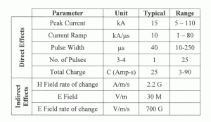
Lightning is the release of an accumulated charge in cloud formations to the earth, and frequently between clouds. The release of electrical charges from cloud to earth is carries the potential of millions of volts, current flows of over 100 kA, and with pulse widths of tens of microseconds. A series of pulses are possible, with rise times of each pulse being around 1 microsecond. Table 1 show some key parameters associated with a lightning discharge.
While there is a considerable variety in each lightning strike, the industry uses standardized waveforms to represent “typical” lightning activity. The most popular waveform is the 8×20 pulse, which is illustrated in the inset in time domain, and in the main curve as frequency domain. Other waveforms are used, including a 1.2×50 for voltage impulses (a rise time of 1.2μs and a pulse width of 50µs, defined similar to the 8×20µs impulse. However, the frequency content for most waveforms is usually similar and almost always shifting frequency less than a decade.

The small inset of Figure 1 shows the 8×20 waveform, time domain view. The rise time and pulse width are shown, as well. The main plot is the frequency domain for this waveform. If we look at the energy content for this idealized lightning impulse, about half the energy is in the first 7 harmonics, or below about 0.12 MHz. In addition, there is very little energy above 1 MHz. So our threat (electrically speaking) is more than three decades from the communication bands (1MHz compared to 5GHz).
Characterizing RF Transmission Performance
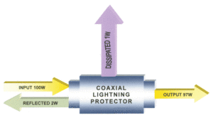
Coaxial protectors are transmission line components and are usually rated by the ability to conduct the desired signal through with minimal loss, and a low level of reflected signal (VSWR). When RF energy is put through a protector, it is conducted through, reflected back, and dissipated as heat, in some combination. Never does the full input energy equal the output energy. For example, in Figure 2 we illustrate a coaxial protector in an RF transmission line; the reduction in the signal through the device is called insertion loss the insertion loss would relate to the output and the input power levels, and is 10 x log(97/100) or approximately 0.13 dB. The reflection is compared to the input and is called return loss, and in this example would be 10 x log(2/100) or 17dB. The 17dB return loss can also be stated in standing wave ratio and would equate to a VSWR of 1.33. The coaxial protector also has RF power limits, but these are typically not critical for most lower power (below 25W) transmitters.
Characterizing Protection Performance
Protectors have two main parameters to characterize protection; current capacity and let-through. Current capacity is the maximum current that can flow on the center conductor. The most common ratings are either;
a. The current for 10 pulses where the protector is still operating afterward, both in terms of passing the RF energy and protecting.
b. The ability to protect against one single impulse, and continue to pass RF energy afterwards,
c. The ability to protect against one impulse, but not fully meet RF performance criteria afterwards.
Make sure that you are comparing the same type of peak current parameter when you select the protector.
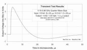
Let-through is the output of the protector when a standardized impulse is applied to the input. In most cases the input is a voltage (open circuit) waveform of 1.2×50µs and a current (short circuit) waveform of 8×20µs. The input levels are usually 4kV and 2kA, or 6kV and 3kA. The output of the protector is burdened by 50µ, and the resulting waveform (dramatically reduced from a 6kV and 50 µs wide impulse) is measured, and two principal parameters are extracted. The first let-through parameter is the peak output voltage. The peak voltage represents the voltage that the RF port should be able to take in without dielectric failure or component failure. The second let-through parameter is the energy, in Joules, deposited into the 50 Ωburden.
Energy in J = 1/50 ∫v(t)2dt
Where J is the energy in Joules, v(t) is the voltage as a function of time. To give a sense of the numbers here, for a protector that has a “square wave” output of 500 volts for 0.1 microsecond, the energy would be 0.1×10⁻⁶ seconds x 500V2 / 50Ω or 500 μJ. The actual integration is typically performed using numerical techniques. This represents the energy that the RF port would need to tolerate without thermic failures.
While all protectors have let-through, the level of energy and voltage is usually dramatically reduced from the magnitude of the original transient. However the let-through should be coordinated with the radio input circuits.
SELECTING PROTECTION ALTERNATIVES
RF Only Solutions
If the protector is only required to pass the RF energy in the 4 to 6 GHz band the protector can take advantage of the separation (of over 3 decades) of the lightning threat frequency (below 1 MHz) content from the required pass band (above 4.5 GHz). This suggests why a band pass type protector can provide good protection. The most popular band pass protectors utilize a high current capacity short circuit shunt from the center conductor to the shield. The highest quality protectors match the ampacity of the shunt with the connector center pin, so that N connectors are capable of 65kA 8×20 µs pulses.

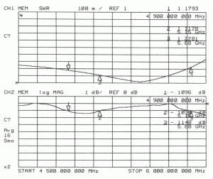
A quarter wave stub protector is a very popular implementation of this device and will provide excellent protection, both in terms of peak current capability and reduction of the transient. The RF pass characteristics of the devices in Figure 3 show remarkable performance, as shown in Figure 4. While this example is for a 5.15 to 5.88 GHz protector, performance is very good at 4.9 GHz. Units that have a wider bandwidth (from 2.4 to 6 GHz) and units optimized for 4.9 GHz are also available in the industry. Quarter wave protectors, while they have exceptional capability, tend to be more expensive than lower performance alternative protectors. Figure 5 illustrates how the lightning let-through of a quarter wave protector for 5 to 6 GHz has a low peak voltage and resulting low energy. Also, the fundamental harmonic content associated with the output has a frequency of about 25 kHz. It follows that there is very little in band (above 4.9 GHz) energy content, so the input band pass filter of the radio will provide further significant attenuation of the lightning energy. There is little value to be gained by use of a dc block type energy limiter within the protector. In fact, dc blocking limiters will make the protector uni-directional (able to accept the transient from one side only). It is preferred to use bidirectional 65kA rated quarter wave stub protectors for the maximum protection capability in 4-6 GHz applications.
DC and RF Solutions
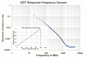
The presence of dc on the center conductor has significant implications for a coaxial protector in 4-6GHz applications. In this case the protection component is a Gas Discharge Tube (GDT), which is a high voltage triggered shunting device. Normally in an open circuit state, the GDT is triggered when lightning activity imposes a high voltage on the center conductor. The GDT will then shunt to ground and remove the energy or voltage on the center conductor. As shown for an ideal GDT in figure 6, the frequency domain of the output of a GDT protector has “shifted up” the energy content, due to truncation of the lightning waveform at about 100ns. However, there is very little energy above 1 GHz, which is still below most radio input filters for 4.9+ GHz operation. However, there is a high voltage peak of a few hundred volts, for a duration of approximately 100 ns. The input to most radios can tolerate this impulse, but this should be confirmed.
After the transient ceases, the GDT will return to its high resistance state and allow normal RF and low voltage dc propagation through the protector. GDTs are the workhorse of the protection industry, and high quality GDTs have the highest transient current capacity of any similar component of their size. Traditional GDT based protectors use a protective component rated for 5kA to 20kA for 8×20 current impulses. Engineers need to be careful here, the peak capacity of protectors can vary greatly and the quality of the GDT is a significant factor in performance.
The problem with most GDT based protectors, which are required when passing dc, is that RF performance from 4GHz to 6GHz usually deteriorates severely. Insertion losses of 0.5 or significantly well over 1 dB are not uncommon. This high loss means a reduction of communication range, which will impact critical applications.
The technical challenge in designing a GDT based device is extending the protector to the higher frequencies of 4-6GHz while minimizing insertion loss and VSWR, in conjunction with retaining maximum transient capability. NexTek has optimized performance protectors using medium capacity GDTs which have RF performance optimized to 6 GHz; these are shown in Figure 7. These protectors’ RF performance, as shown in Figure 8, provides the best combination of excellent RF performance and protection capability, while maintaining only a 0.1dB Insertion Loss and being able to pass dc.

As shown in Figure 9, GDTs trigger after the voltage exceeds the trigger level for a very short time. For example, the GDT used in NexTek 6 GHz protectors reaches about 600V peak and is clamped to a very low voltage in about 100ns during the simulated lightning impulse.
OTHER FACTORS AFFECTING LIGHTNING PROTECTION
Minimizing Direct Lightning Strikes
The protection capacity of the protector can be lowered if the risk of direct strikes is reduced. The small physical size of an antenna in the 4 to 6 GHz range allows location of the where lightning cannot directly strike easily. The antenna can be protected by locating it under an overhang, below another antenna or mast structure, or by mounting a projecting grounded metal shielding member above the antenna. In these cases a long service life can be obtained.

Proper Grounding is Critical
Be sure to install the protector near the building entry. It is preferred that the protector be within 1m (3’) of the cable entry into the building. The grounding wire or strap to the protector should be about twice the conductor area of the coaxial shield, with a minimum of 10 AWG (3.5mm2). The grounding structure system should be able survive high current injection levels at low voltages, and able to drain the current into the soil.
Intermediate Frequency (IF) Lines are Lower Frequency
In some applications the indoor unit is separated by an outdoor unit by a cable with IF and dc power. This IF is usually much lower frequency than the actual transmission frequency, so lower frequency protectors with higher transient capability may be acceptable for this location. The antenna side of the outdoor unit may still benefit from a quarter wave (RF only) protector.

Complete Protection Plan
This article introduces the concepts of protecting coaxial cables from lightning. Lightning protection is a serious concern for equipment investments, but more importantly a significant safety issue. Lightning can enter all conductive elements on a site including power, telephone and cable lines, pipes, and the building structure. In order to ensure complete protection, follow codes and regulations and consult a lightning protection expert.
References
Lightning Facts, Copyright 1997, Jim Lux, home.earthlink.net/~jimlux/lfacts.htm
Mike Holt Enterprises, Inc. • www.NECcode.com
National Lightning Safety Institute, http://www.lightningsafety.com


