Radiated and conducted emissions measurements are often comprised of both narrowband and broadband sources. So what differentiates “narrowband” and “broadband” signals?
Narrowband Versus Broadband Signals
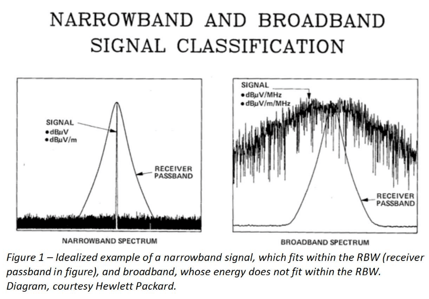
The definition of whether a signal is narrowband or broadband as measured using a spectrum analyzer, depends entirely on the receiver bandwidth (resolution bandwidth, or RBW). For commercial EMI signals, the test standards define what the RBW should be.
For example, when measuring from 150 kHz to 30 MHz, the RBW is specified as 9 kHz. For frequencies between 30 and 1000 MHz, the RBW is 120 kHz. This was originally defined as the typical broadcast radio (AM and FM) receiver bandwidth.

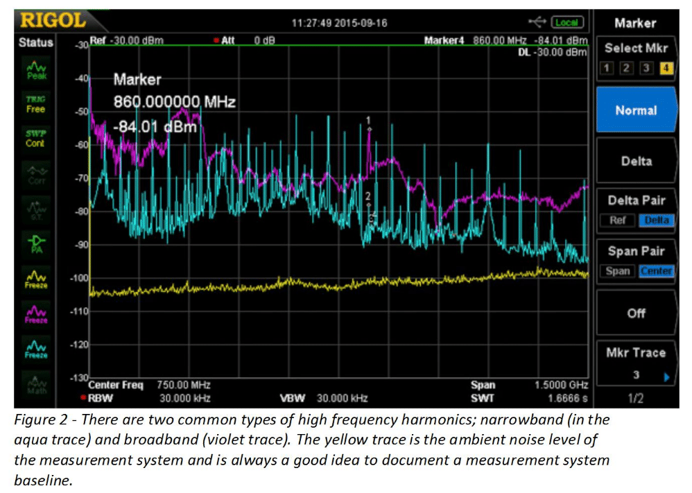
Figure 2 shows the difference between the two measured sets of harmonic signals as we’re looking from 9 kHz to 1.5 GHz. The RBW has been adjusted to 30 kHz for this example. Typically, DC-DC converters or data/address bus data will appear as a very broad signal with several resonant peaks (violet trace in Figure 2), while crystal oscillators or high speed clocks (anything with fast switching edge speeds) will appear as a series of narrow spikes (aqua trace in Figure 2). Unless the product is designed for EMC compliance, both these types of signals can radiate or conduct high frequency energy well into the mobile phone bands.

Note that by reducing the RBW way down to 1 kHz or so, you’ll be able to start resolving the harmonics from DC-DC converters or other switching power supplies. You’ll see that the signals are actually narrowband! This illustrates that a series of harmonic signals can be both narrowband and broadband. It all depends on the RBW.
Rohde & Schwarz has two useful references that describe this concept in much more detail, and will be presenting a webinar on this subject during the EMC Live event April 25, 2017. EMC.Live You can find the recorded presentation by clicking on https://emc.live/2017/narrowbandbroadband-not-just-arcane-discrimination-key-system-level-emc-demonstration/.
Presentation details:
Narrowband/Broadband – Not Just An Arcane Discrimination, but the Key to System-Level EMC Demonstration
Laboratory demonstrations show why modern EMC testing uses the spectrum analyzer noise floor measurement as opposed to the older method of sampling radio channels and listening for noise. The attendee will witness a demonstration of the effects of narrow and broadband noise on both the ability of a victim radio to properly receive a signal, and also the ability of a test engineer to properly discern if there is interference.
References:
1. Rohde & Schwarz, Measuring with Modern Spectrum Analyzers, https://cdn.rohde-schwarz.com/pws/dl_downloads/dl_application/application_notes/1ma201_1/1MA201_9e_spectrum_analyzers_meas.pdf
2. Rohde & Schwarz, Making Spectrum Measurements with Rode & Schwarz Network Analyzers, https://cdn.rohde-schwarz.com/pws/dl_downloads/dl_application/application_notes/1ez62/1EZ62_0e.pdf


