J M Woodgate BSc(Eng) C.Eng MIET SMIEEE FAES HonFInstSCE
J M Woodgate and Associates
jmw@jmwa.demon.co.uk www.jmwa.demon.co.uk
These days, it’s common practice to buy-in mains input filters in the shape of metal boxes with four or five terminals. The supplier’s lists may be consulted, and advice sought, but often the same filter as was used for a previous product is called up, without too much deliberation. A filter is a filter is a filter, after all.
Well, no, they are not all the same. Let’s consider what we are asking the filter to do. It’s quite important at this time, because EMC requirements are being extended both upwards from the 40th harmonic of the power frequency and downwards from the historic 150 kHz lower limit of ‘high frequency emissions’. For some products, requirements already exist down to 9 kHz and there is no low-frequency limit now in the standard, CISPR 11/EN 55011, for ‘industrial, scientific and medical’ equipment, or in the new Radio Equipment Directive.
Whiter we want it or not (but we mostly do want it), the filter acts both on energy incoming from the power system (an immunity issue) and energy leaving the product and entering the power system (an emission issue). For both flows, we have two modes: differential mode, in which a voltage appears between the two power conductors, and common mode, in which both conductors have the same voltage relative to local ground. In the case of three-phase, three-wire supplies, the filter configuration is more complicated, but for three-phase, four wire supplies, each phase is treated as if it were a single phase. Examples can be seen at:
http://www.filterconcepts.com/three_phase/3f_series.html
How we can attenuate these flows depends on their source impedances. Clearly, it’s not much use connecting a capacitor across a low-impedance source to shunt current away, because plenty of current is still available, and it’s equally futile to connect an inductor in series with a high-impedance source. This is, in fact, an example of a far more general concept.
It’s useful to think in terms of energy, rather than voltage or current. Energy is the product of power and time and is the ‘electricity’ we pay for. There are two ways a filter could work; it could absorb unwanted incoming energy or it could refuse to accept it. Absorbing or dissipating filters do exist (those using iron-dust cored inductors, for example), but the energy appears as heat and the amount is often too much to accept. So most filters are ‘reflecting’; they refuse to accept incoming energy and push it back to the source.
They do that by having an input impedance very different from the impedance of the source. The ‘Maximum Power Theorem’ says that the optimum energy transfer occurs when the resistances of source and load (input resistance of the filter) are equal and their reactances are equal and opposite (i.e. one inductive, one capacitive). But our reflecting filter wants the worst power transfer we can get, so the resistances need to be very different and, if possible, both reactances have the same sign.
So what is the impedance of the power network? EMC standards committees have put a lot of work into this difficult subject. We know that, at the power frequency, for ordinary wall-sockets it must be in the region of 0.1 Ω to 1 Ω from voltage-drop considerations, but that takes account only of conductor resistance. The network also has what can be represented as a lossy inductor in series, and this model works reasonably well up to about 9 kHz. In Europe, the ‘average’ value is close to 800 µH, although that approaches the average of zero and infinity if we take in all the outliers including long rural overhead transmission. The ‘average’ values for other power systems can be found in IEC TR 60725.
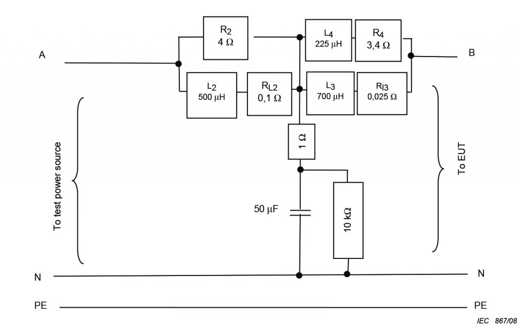
A network representing the impedance of 230 V 50 Hz 16 A circuits in Europe from 2 kHz to 9 kHz is given in IEC 61000-4-7 and is shown below in Figure 1, but a new and more accurate network is under development.

Figure 1 Artificial mains network for 16 A current and below
(from IEC 61000-4-7)
For frequencies above 9 kHz, we have the information on ‘line impedance stabilizing networks’ (LISN) or ‘artificial mains networks’ (AMN) in CISPR 16-1-2/EN 55016-1-2. For 9 kHz to 150 kHz, an impedance of 5 Ω in series with 50 µH is given, with a parallel 50 Ω resistance, while for the range 150 kHz to 30 MHz an impedance of 50 Ω in parallel with 50 µH is given. There is now a third network, for 150 kHz to 100 MHz, which is 50 Ω in parallel with 5 µH in series with 1 Ω. However, some of these values are ‘traditional’, and again tend to be the average of zero and infinity. Nevertheless, their use doesn’t result in any proposal to change them on the grounds that something else is demonstrably better.
However, the impedance at any particular wall-socket is undetermined and may even vary, according to what other loads are on the same circuit and how the supply network is configured at that time of day. So we want our filter to be very tolerant of source impedance and not, for example, show any resonant behaviour in conjunction with any likely supply reactance.
The impedance of the load can be very problematical. It is very often a full-wave rectifier, so extremely non-linear. We know from experience of EMC problems in the field that the circuit is transparent from the filter capacitor to the mains filter ‘output’, because if the capacitor dries out so that its capacitance drops to a much lower value, the high-frequency emissions coming from processes inside the product circuits considerably increase in amplitude, typically by more than 20 dB.
Note to designers: Consider using a high-temperature (105°C or even 135°C) part, with a generous ripple-current rating, to combat this effect. A 100 nF capacitor in parallel may help, too.
There are two sources of high-frequency energy that propagate from the product to the power system; commutation spikes from the rectifier diodes and whatever high frequencies that circuits in the product generate that can be modelled as a voltage in series with the effective load resistance of the rectifier. There may well also be an active power-factor correction circuit preceding the AC side of the rectifier.
For the ‘traditional’ frequency range from 150 kHz upwards, the sources (power network and rectifier or whatever in the product) are assumed to have high impedances, so should be faced in the filter by capacitors, between the live conductors to present a low impedance to differential mode energy , and equal values from each conductor to ground to do that for common-mode energy.
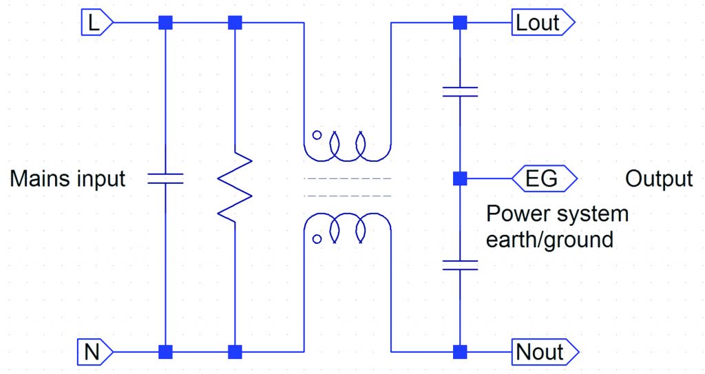
Simple filters for low-power products therefore have a modified π configuration, (strictly an O-configuration, because it has inductors in both ‘legs’) as shown in Figure 2. The inductors are rather special and are called a ‘common-mode choke’. The two windings, as shown are on a single core, usually ferrite, and the windings are in the same direction, as shown by the ‘phasing dots’. So for common-mode currents, that flow in the same direction in the two windings, the inductance is high, but for differential mode currents, including the supply current, the inductance is low, but it is designed not to be very small, so that, in conjunction with the capacitors, it attenuates high-frequency differential-mode currents as well. The capacitor at the input serves to further attenuate differential-mode currents, whichever direction they are flowing. The parallel resistor is there to discharge the capacitor, so as not to leave the plug pins live if the mains lead is disconnected at the wall-socket. As shown in the three-phase filter circuits accessible via the above link, the earth/ground conductor may be carried through the filter by a separate inductor.

Figure 2 Simple mains input filter
Common-mode currents (unwanted emissions or incoming disturbances) flow in the same direction in the two windings, so the effective impedance is much higher. The capacitors at the output attempt to attenuate common-mode voltages while preserving an impedance-balance for the differential mode. ‘Attempt’, because their values have to be restricted so as not to cause an unacceptable amount of current into the ground connection. This is quite a serious issue when large numbers of products, all contributing only a milliamp or so, are connected to the same ground network. In the Americas, products connected to 240 V pass equal and opposite ground currents from the two live conductors, so contribute no net ground current. (This is because the distribution system is 120 V-0-120 V, with the voltage in one live conductor inverted with respect to the other, so that between the live conductors the voltage is 240 V.)
This configuration is indeed suited to frequencies where the mains and load impedances are relatively high, because the capacitors tend to short-circuit the sources, but that doesn’t work well for low-impedance sources, and at frequencies well below 150 kHz, just now coming under the EMC spotlight, the mains supply and the load impedances are not high at all. So something more is necessary, at least at the input, when differential-mode lower-frequency energy needs to be controlled and the source impedance is lower.
The solution is to add individual inductors in each ‘leg’ of the filter, upstream of the parallel capacitor. Now the low source impedance of the mains supply meets the high impedance of the inductors and energy flow is restricted. This solution is likely to be needed more in the future, as requirements for low-frequency immunity, which are already in EMC Basic standards but not widely called up in product standards, and future standards on emissions, become regulatory requirements.
The same series inductor solution is likely to be necessary at the output end of the filter if the load is something, such as an inverter, that produces emissions in the 2 kHz to 150 kHz range, as many do. So the small metal boxes we use at present may well need to grow in size (and, of course, cost) in the next few years.
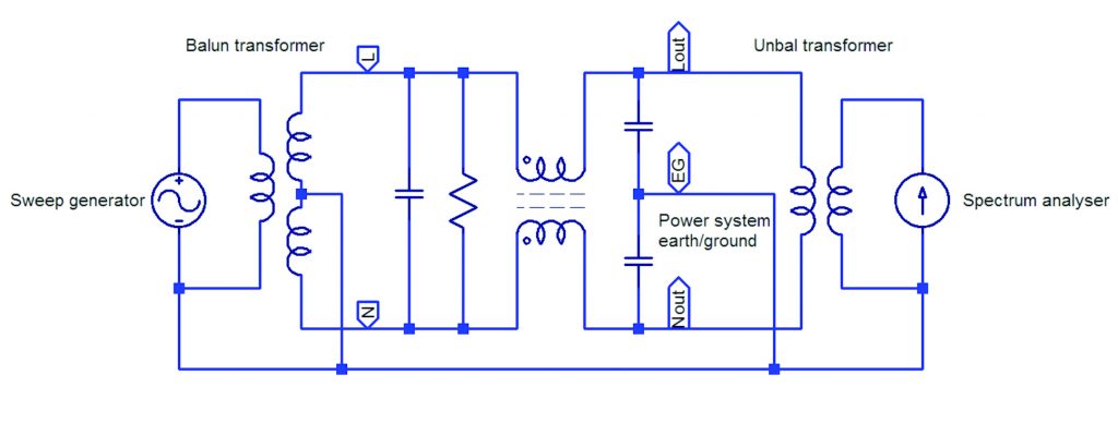
It is necessary to be very cautious about published specifications of filter attenuation. These are often measured with 50 Ω resistive source and load, which is easy to do but far from realistic. Many manufacturers also publish results under other conditions, such as a 0.1 Ω source and a 100 Ω load and vice versa, as described in Annex C of the International Standard CISPR 17/EN 55017 (which includes test set-ups not only for complete filters but also for individual components), but that is not necessarily much more realistic. And it doesn’t fully explain how to test. It does specify that the filter characteristics are likely to vary with the mains-frequency current flowing, but it does not elaborate that the differential-mode attenuation (the voltage between L and N at the output divided by the corresponding voltage at the input) should really be measured with balanced radio-frequency signals, while the common-mode attenuation should be measured with unbalanced (i.e. one side earthed/grounded) signals. But the standard LISNs only have L and N outputs, whose output is the common-mode voltage plus or minus half the differential-mode voltage.
Figure 3 shows a set-up for measuring differential-mode attenuation in a balanced configuration. Arrangements for applying mains voltage and a load are not shown.

Figure 3 Measuring differential-mode attenuation in a balanced configuration
Using this configuration correctly shows the effects of parasitic capacitances inside the filter assembly.
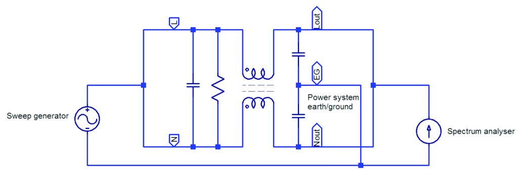
Figure 4 shows a set-up for measuring common-mode attenuation. Again, the arrangements for applying mains voltage and a load are not shown.

Figure 4 Measuring common-mode attenuation
Neither of these set-ups show the transformers necessary to do the 0.1 Ω/100 Ω tests.
It is really necessary to measure filter performance in the product it is to be used in, even if it takes some ingenuity to make realistic measurements. A decision has to be made whether to include a standard Line Impedance Stabilizing Network (LISN), which assumes that the mains supply ‘looks like’ 50 Ω at high frequencies, or to use a hopefully representative supply without a network.


