Alastair R. Ruddle, Ph.D.
Computational Electromagnetic Specialist, MIRA Limited
Radiated electromagnetic emissions measurement standards for road vehicles were developed at a time when the main threat posed by radio-frequency noise from vehicles was interference to broadcast transmissions from spark ignition systems. Since that time, however, on-going technological developments have resulted in changes in the nature of both the emissions from vehicles and the radio-based services under potential threat. This raises questions as to whether the existing test methods remain appropriate for modern vehicles.
The developments that impact on electromagnetic emissions from modern vehicles arise from the following technological trends in the automotive industry:
- Replacement of traditional mechanical systems with mechatronic solutions (anti-lock braking systems, steer-by-wire etc.).
- Use of more sophisticated technologies to deliver existing electrical and electronic functions (PWM control for vehicle lamps, faster processors etc.).
- Moves towards greater integration between systems in order to provide enhanced functionality (e.g. stability control systems).
- Introduction of new functions and services based on wireless communications and operating at increasingly high frequencies (vehicle telematics, Bluetooth, radar-based adaptive cruise control etc.).
- Wider exploitation of lightweight materials, rather than traditional steel, in order to improve energy efficiency.
- Increasing deployment of alternative powertrain technologies (e.g. battery, hybrid and fuel cell vehicles).
The latter prompted amendments in the fifth edition of CISPR 12 [1], which is referenced by the Automotive EMC Directive [2], requiring vehicles with electric powertrain to be operated at 40 km/hr in order to ensure that emissions from these components are taken account of. A further amendment to CISPR 12 [3], which includes an additional requirement for hybrid vehicles that both drive systems should be operational during the measurements where possible, are referenced by UNECE Regulation 10 [4], which will replace the Automotive EMC Directive for EU whole vehicle type approval purposes with effect from November 2014 [5]. Amendments to UNECE Regulation 10 adopted in 2012 also describe new radiated emissions test requirements relating to on-board conductively-coupled electrical charging systems [6]. Wireless inductive charging of vehicle traction batteries, which is currently of growing interest, will necessitate the development of further emissions test requirements.
However, there may be emissions at frequencies outside the existing vehicle emissions test band, and conventional vehicles may also be equipped with systems that are dormant until the wheels are in motion. Thus, existing test methods may be becoming less relevant as new technology is introduced. This article gives an overview of an investigation into possible alternative approaches for measuring vehicle electromagnetic emissions that was motivated by these issues.
EXISTING VEHICLE EMISSIONS MEASUREMENT PRACTICES
Unlike the emissions testing standards used by many other industries, such as CISPR 22 [7], there is no requirement for height scanning of the antenna and rotation of the test object in order to identify the maximum emission levels. The approach for vehicles is based on more restricted “snapshots” for fixed test configurations.
Current vehicle-level radiated emissions test requirements ([2], [5]) specify broadband and narrowband emissions measurements over the band 30–1000 MHz using an antenna at a fixed point relative to the vehicle. Broadband emissions are classified as signals with bandwidths that exceed the receiver bandwidth, and have pulse repetition frequencies that are smaller than the receiver bandwidth. Narrowband emissions are classified as signals with bandwidths that are smaller than the receiver bandwidth, and have pulse repetition frequencies that are greater than the receiver bandwidth. In CISPR 12, both broadband and narrowband measurements are carried out using a receiver bandwidth of 120 kHz.
For conventional vehicles, broadband measurements are carried out using a quasi-peak detector with the engine running at constant speed (1500 rpm), primarily to detect emissions from the spark ignition system. Vehicles with electric powertrain are required to be operated at 40 km/hr (or maximum speed if this is lower), either on a dynamometer under negligible load or in a free-wheeling mode with the driven wheels raised up using non-conductive axle stands. As quasi-peak measurements require a significant dwell time, a common approach is to use peak measurements to quickly identify those frequencies that are sufficiently close to the limits to merit the slower quasi-peak measurements. Narrowband measurements are carried out using an average detector with the vehicle switched on but without the engine running, in order to detect emissions from on-board electronic modules.
The most common test configuration is an open area test site (OATS), or a semi-anechoic chamber (SAC), with an antenna mounted 3 m high at a distance of 10 m from the side of the vehicle and aligned with the center of the engine (as illustrated in Fig. 1). However, the standards also permit measurements at a reduced distance of 3 m, with the antenna height reduced to 1.8 m. The limits for the 3 m measurements are based on the 10 m limits with a 10 dB increase, reflecting free-space attenuation for a point source.
The emission level is simply taken to be the maximum of the values recorded on either side of the vehicle. Nonetheless, sweep times can be significant, even without the requirement to identify the direction of maximum emission, so broadband antennas are normally used in order to minimize test disruptions.
Although there is an SAE Recommended Practice [8] for measurement of radiated electric and magnetic field emissions at lower frequencies (from 9 kHz to 30 MHz) from vehicles with electric powertrain, this is not a requirement and there are no similar recommendations for the testing of conventional (i.e. internal combustion engine) vehicles at these frequencies.
INVESTIGATION OF ALTERNATIVE TEST METHODS
Measurements based on both the conventional fixed geometry of CISPR 12 and the height/azimuth scanning approach of ANSI C63.4 [9] were carried out at frequencies from 9 kHz to 1000 MHz on an open area test site (OATS) for a range of seven different vehicles using the static test modes of CISPR 12. Various practical issues limited the ability to replicate these methods exactly. In earlier investigations of alternative powertrain vehicles at low frequency [10] it was found that measurements at the standard 10 m distance were impracticable because of high and fluctuating ambient signals. In this work, therefore, the measurement distance was reduced to 3 m for frequencies below 30 MHz.
A bilog antenna at 3 m height was used for measurements in the band 30–1000 MHz, for both horizontal and vertical field polarizations. For the measurements below 30 MHz, an active loop antenna at a height of 1.8 m was used to detect transverse and radial horizontal magnetic fields, and an active monopole antenna mounted at a height of 1 m was used to measure the vertically polarized electric field.
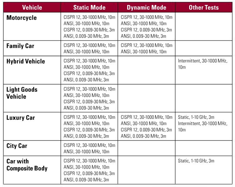
As there are vehicle systems that are dormant unless the wheels are in motion, measurements were also made for a dynamic, steady-state operating mode that was achieved by raising the driven wheels so that the powertrain could be engaged in free-wheeling operation (as used for electric powertrain testing). For two vehicles, emissions from various intermittent sources, and in the band 1–10 GHz, were also investigated. The antennas used above 1 GHz included a bilog, a dual-polarized horn and a double-ridged horn. The range of sample vehicles and the tests that were carried out on them are summarized in Table 1 below.
For the ANSI-based measurements with antenna height and angular scanning, the vehicle wheelbase was centred on the turntable axis and the antenna was positioned at a distance of X m as indicated in Fig. 2, such that the separation between the antenna and the vehicle was at least X m (where X=10 m for measurements in the band 30–1000 MHz and X=3 m for measurements in the band 9 kHz to 30 MHz).

Preliminary scans, which were needed in order to identify emissions frequencies for more detailed investigation, were carried out on both sides of the vehicle at fixed heights of 1 m for vertical polarization and 2 m for horizontal polarization. The selection of these particular configurations for the preliminary scans was based on practical experience of these types of measurements. As in the method based on CISPR 12, the measurements were carried out using a quasi-peak detector for broadband emissions and an average detector for narrowband emissions. Where time permitted, such as when few emissions were found, additional data was collected at different test positions.
RESULTS FOR FREQUENCIES BELOW 30 MHZ
Low frequency measurements were not carried out for the city car or the family car, and only the motorcycle and luxury car were tested in the steady-state dynamic mode. Measurements for the hybrid, light goods and composite vehicles were limited to the static mode only.
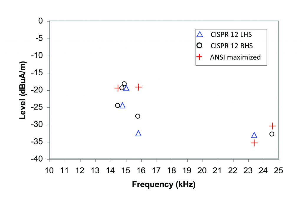
No low frequency emissions were detected from the motorcycle in either static or dynamic modes. The light goods vehicle (only tested in the static mode) provided narrowband emissions at 16 MHz only, which probably arises from a control module clock signal. For the composite vehicle, broadband emissions were found for two polarizations (see Fig. 3).
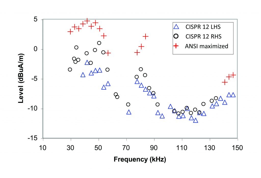
Broadband emissions were also detected from the hybrid vehicle (see Fig. 4), together with a few narrowband emissions. Both static and dynamic measurements were carried out for the luxury vehicle. In this case a few broadband emissions were found, but for the static mode only, while a large number of narrowband emissions were obtained for the dynamic mode only (see Fig. 5). No reliable emissions were detected from any of the vehicles in measurements using the active monopole antenna.

Results for Frequency Range 30–1000 MHz
Measurements in this band were carried out for all of the vehicles in the conventional static mode. The motorcycle, family car and luxury cars were also tested in the steady-state dynamic mode.
For the family car, the only emissions detected were broadband for vertical polarization, which were present in both static and dynamic modes. The results obtained from the luxury car, however, were limited to a few broadband emissions, in the static mode only, again only for vertical polarization.
Almost no emissions were detected from the light goods vehicle. Only broadband emissions were detected from the hybrid vehicle, while for the composite vehicle narrowband emissions were obtained for vertical polarization and broadband emissions were detected for both polarizations. For the city car, both broadband (see Figure 6) and narrowband emissions were detected, mostly for vertical polarization.

For the motorcycle, broadband emissions were detected for both vertical and horizontal polarization, in both static and dynamic modes (shown in Figs. 7–8). Narrowband emissions were also obtained for the motorcycle in both static and dynamic modes, although very few such emissions were detected for horizontal polarization.
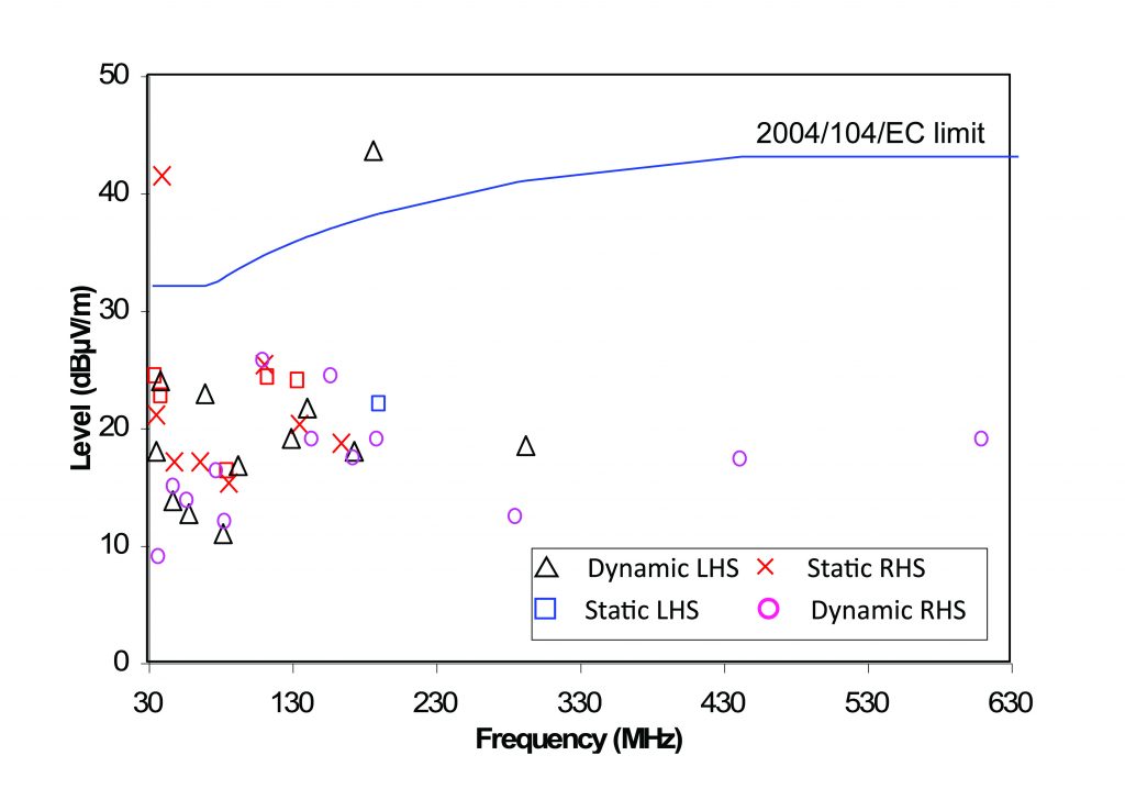
Results for Frequencies Above 1 GHz
Measurements based on the CISPR 12 approach were also carried out for the static mode over the band 1–10 GHz in an anechoic chamber, but only for the luxury car and for the composite vehicle.

The emissions were monitored using a receiver configured with a 1 MHz measurement bandwidth and a 500 kHz frequency increment. The antenna was positioned at 1 m height and placed at a 3 m distance (due to space constraints in the anechoic chamber) and at multiple positions alongside the vehicle (because of the narrower beamwidths of the antennas at these frequencies). The test positions investigated included:
- Position 1 – driver’s side, aligned with rear axle
- Position 2 – driver’s side, aligned with midpoint
- Position 3 – driver’s side, aligned with front axle
- Position 4 – front, aligned with vehicle axis
Broadband emissions were found for both polarizations at frequencies up to 3 GHz for the luxury car, and at up to 6 GHz for the composite vehicle. Results for the latter were clearly clustered by position for horizontal polarization (see Fig. 9), but not for vertical polarization (see Fig. 10). However, no narrowband emissions were detectable (using a criterion that the emission should be at least 4 dB above the noise floor) from either of the vehicles tested at these frequencies.
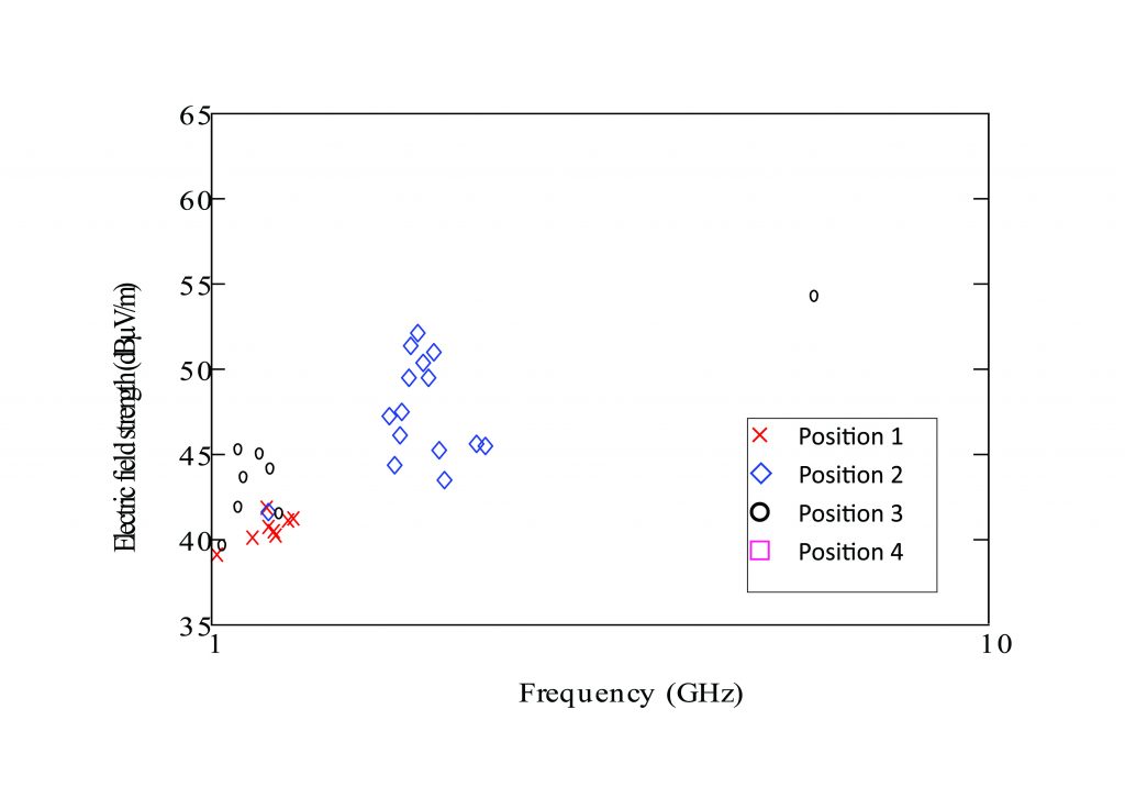
Intermittent Sources, 30–1000 MHz
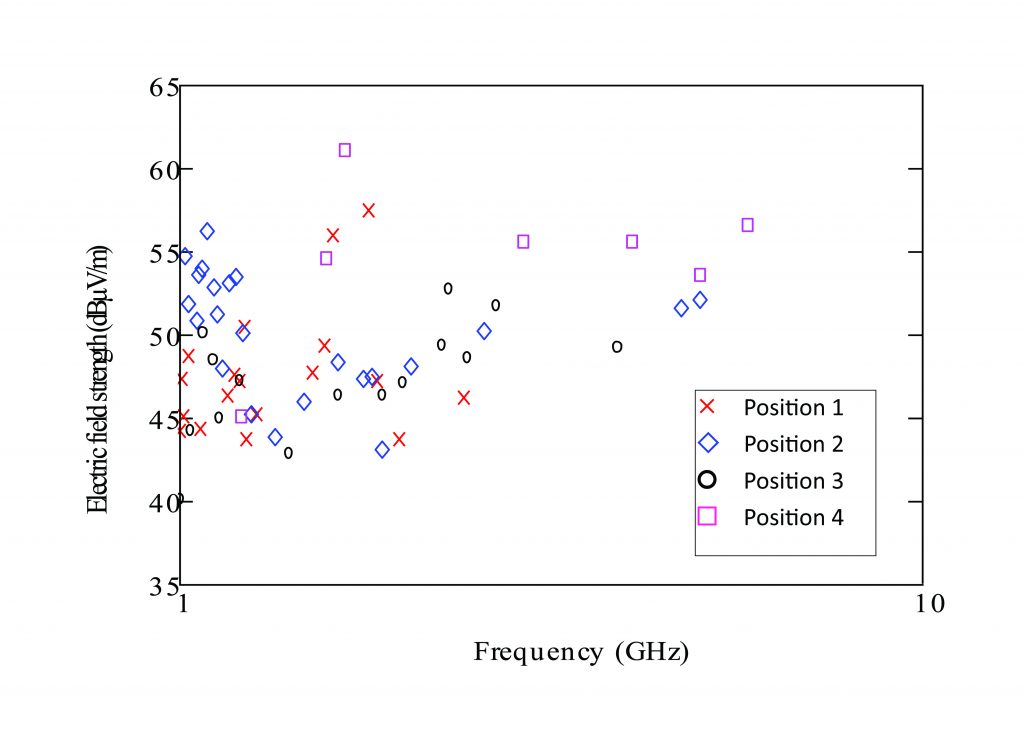
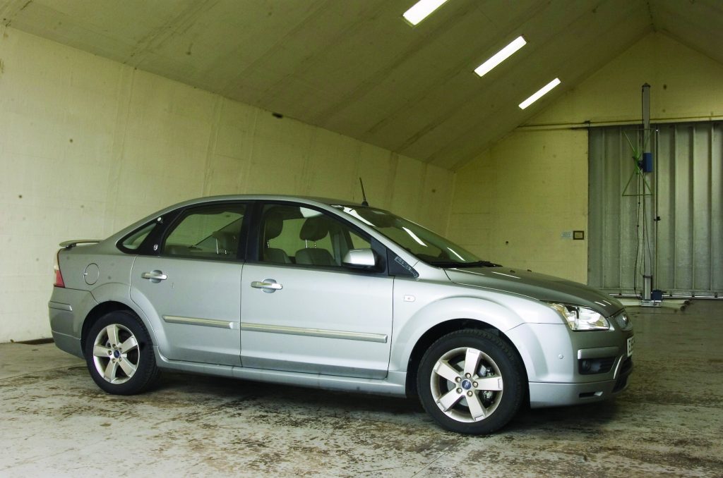
In order to investigate the emissions from electronic systems under more realistic driving conditions, measurements were carried out in a large semi-anechoic chamber (SAC). The SAC (shown in Fig. 11) is equipped with a dynamometer, which allows vehicles to be operated under road-load conditions whilst carrying out EMC measurements. Thus, vehicle emissions can be measured under realistic driving conditions, including during acceleration and deceleration cycles, using this facility. A further advantage is that the emissions from vehicle sources are more easily identified and quantified in the SAC, which minimizes the impact of high ambient signals such as broadcast transmissions.
Due to the relative geometry of the dynamometer in the SAC, the measurements were made from the front of the vehicle, with the vehicle positioned on the dynamometer and the measuring antenna (a bilog) positioned 10 m forward of the front axle at a height of 3 m. Measurements were made during operational cycles of each of the following systems:
- electric window operating (window wound up and down until sweeps were completed);
- windscreen wipers operating in fast and slow modes;
- rear window heater on;
- internal fan heater operating in fast and slow modes;
- indicators operating on driver’s side;
- headlights on;
- engine idling at 1500 revs/min (for comparison with standard CISPR 12 measurements).
For these sources, five “maximum hold” measurements with the peak detector (each lasting 10 seconds) were carried out while the system under test was operated.
Measurements were also made during the following dynamometer drive-cycles (the sweep time varies as detailed below for specific drive-cycles):
- acceleration to 50 km/h (over a period of 20 s);
- deceleration from 50 km/h (over a period of 20 s);
- constant 50 km/h.
The fan heater and electric windows produced emissions that approached, but did not exceed, the limits. However, emissions at levels above the limits were observed for the constant speed and acceleration/deceleration modes. For the luxury car, emissions of up to 10 dB above the limits were found at constant speed for vertical polarization. Thus, there may be some merit in investigating vehicle emissions under constant speed conditions, which can be achieved using current CISPR 12 methods if a dynamometer is available.
Measurement Issues
In these comparison of CISPR 12 and ANSI-based methods, the ANSI-based values were generally higher, and markedly so in some cases, whereas the CISPR 12 approach allowed larger numbers of emissions to be identified much more rapidly, but at the cost of limited amplitude and directional information. This is due to the time taken to maximize the emissions in the ANSI-based approach through height and angular scanning. In this study, the time that was available for the ANSI-based measurements was twice that allocated for the measurements based in CISPR 12. Furthermore, the emissions frequencies identified using the two methods are not always identical. This perhaps resulted from differences in the relative geometry of the vehicle and the antenna between the CISPR-based measurements and the preliminary scans used in the ANSI-based approach.

Comparison of measurements using the two approaches on real vehicles on the OATS was also complicated by apparent drift in the levels during the time taken to maximize the emissions. Thus, in many cases the “maximized” results were in fact lower than those recorded from the preliminary scan. This problem did not arise in measurements carried out using a noise source to excite the wiring of two of the vehicles (in a dormant state), which were used to investigate the correlation between measurements at 3 m and 10 m distances.
Consequently, the emissions identified from the two methods were not identical and there were emissions, often at high levels from the CISPR 12 measurements, which were missed using the ANSI method. This, together with the drift problem and the fact that the number of emissions that can be investigated using the ANSI method is limited by the time taken to maximize the levels, suggests that the ANSI results do not necessarily provide a better view of the overall emissions profile than can be obtained using methods based on CISPR 12.
In practice, therefore, both methods have weaknesses in characterizing the emissions profiles of vehicles. A more cost effective approach for improving the spectral and spatial coverage of vehicle emissions measurements could be to use additional sweeps at different fixed measurement locations, rather than the adoption of inherently slower and more limited height and azimuth scanning methods. However, this would mean further expansion of the test requirements.
In the band 1-10 GHz it was not possible to investigate the ANSI-based method due to lack of a suitable turntable in the anechoic chamber. Nonetheless, the greater bandwidth to be covered and the smaller beamwidths of the antennas used in this band resulted in long measurement times for the approach based on CISPR 12.
Conclusions
The measurements carried out in this project, at frequencies from 9 kHz to 10 GHz, demonstrate that emissions are present at frequencies outside the existing vehicle emissions test band, both above 1 GHz and (for magnetic field) below 30 MHz. Thus, there is a case for extending the frequency scope of automotive emissions measurement requirements both above and below the current test band. In order to facilitate this, suitable frequency and emissions limits, as well as appropriate measurement methods, would need to be defined for frequencies above 1 GHz and below 30 MHz.
The investigation of emissions under the steady-state dynamic test condition (with the driven wheels in motion) and from “intermittent” vehicle sources (including acceleration and deceleration cycles as well as systems such as heaters, lights and electric windows) also shows that the operational emissions characteristics are likely to be different from those for the static modes that are currently tested. The steady-state dynamic test condition could be accommodated using current test methods, and can be achieved using “free-wheeling” operation as in this work, although a dynamometer (as used in [3]) provides a more realistic and satisfactory solution. It is therefore recommended that a dynamic steady-state mode should be considered for future development of automotive emissions standards.
The measurements reported here show that both CISPR 12 and ANSI C63.4 based methods have weaknesses in characterizing the emissions profiles of vehicles. These results also suggest that the use of additional sweeps at different fixed measurement locations would perhaps be a more efficient approach for improving the spatial coverage and reliability of vehicle emissions measurements than the adoption of inherently slower and more limited height and azimuth scanning methods. This approach may also be more suitable for alternative powertrain vehicles, which include architectures that combine spark-ignition engines and electric motors, and may employ multiple traction machines (e.g. wheel-mounted motors). However, increasing the number of fixed emissions measurement points would mean further expansion of the test requirements in addition to the expanded frequency scope and steady-state dynamic test mode that are recommended above.
The time taken to complete measurements using the current methods is already considered to be too high by industry, so any movement towards increasing emissions measurement time would not be regarded favourably. However, measuring a wider range of frequencies would inevitably require more time, even using methods based on CISPR 12. Consequently, alternative approaches that could speed up the measurement process would be highly desirable.
Time-domain emissions measurement methods offer much greater speed more traditional frequency-domain approaches (acceleration factors of 10-100 have been reported [11]–[12]), and could therefore allow many more measurement configurations to be investigated within a given time than conventional frequency sweeps. The results obtained in this work suggest that making additional CISPR type fixed measurements is perhaps more beneficial than maximizing a few emissions. Faster, time-domain measurements could be used for this purpose, or to reduce the “search space” by more rapidly identifying emissions that are required to be maximized. Furthermore, time-domain methods are inherently much better suited to the measurement of intermittent sources, for which cycle times are too short for reliable measurements using frequency domain methods.
Measurement of emissions in the 1–10 GHz band was also found to be slow. For radiated immunity measurements, reverberation conditions offer several advantages, such as reducing the power required to achieve high field levels and eliminating the need to illuminate the equipment under test from a particular direction and with a specific field polarization. Furthermore, reverberation chambers are much cheaper to construct than anechoic or semi-anechoic chambers of comparable size as expensive absorbing material is not required. The use of reverberation chambers for achieving faster emissions measurements has also been considered [13], as this test environment provides more comprehensive coverage in terms of emission angles and field polarizations. Methods for measuring both emissions and immunity characteristics are described in IEC 61000-4-21 [14]. In order to achieve the necessary statistical field properties the reverberation chamber must support a sufficiently large number of modes. Although it would be impractical to have a sufficiently large chamber for use at very low frequencies, as for immunity measurements, reverberation chambers become increasingly successful (in that they are able to support increasing numbers of modes) at high frequencies. Thus, a reverberation chamber could be used to rapidly identify significant emissions at high frequencies, perhaps for more detailed investigation using other techniques.
Acknowledgement
The work reported here was carried out as part of a contract from the UK’s Radiocommunications Agency, which is now part of Ofcom (Office of Communications). The report on the study that this article is based on [15] is available from the Ofcom website.
References
[1] CISPR 12:2001, “Vehicles, motorboats and spark-ignited engine driven devices. Radio disturbances characteristics. Limits and methods of measurements”, 2001.
[2] “Directive 2004/104/EC of 14 October 2004 adapting to technical progress Council Directive 72/245/EEC relating to the radio interference (electromagnetic compatibility) of vehicles and amending Directive 70/156/EEC on the approximation of the laws of the Member States relating to the type-approval of motor vehicles and their trailers”, Official Journal of the European Union, No. L 337, 13th November 2004, pp. 13-58.
[3] CISPR 12:2001+A1:2005, “Vehicles, motorboats and spark-ignited engine driven devices. Radio disturbances characteristics. Limits and methods of measurements”, 2005.
[4] UNECE, “Regulation No. 10 – Uniform provisions concerning the approval of vehicles with regard to electromagnetic compatibility”, Add. 9, Rev. 3, 14th August 2008.
[5] “Directive 2007/46/EC of the European Parliament and of the Council of 5 September 2007 establishing a framework for the approval of motor vehicles and their trailers, and of systems, components and separate technical units intended for such vehicles”, Official Journal of the European Union, No. L 263, 9th October 2007, pp. 1-160.
[6] UNECE, “Regulation No. 10 – Uniform provisions concerning the approval of vehicles with regard to electromagnetic compatibility”, Add. 9, Rev. 4, 6th March 2012.
[7] CISPR 22, “Limits and methods of measurement of electromagnetic disturbance characteristics of information technology equipment”, 1999.
[8] SAE Recommended Practice J551-5:2004, “Performance levels and methods of measurement of magnetic and electric field strength from electric vehicles, broadband, 9 kHz to 30 MHz”.
[9] ANSI C63.4, “American National Standard for Methods of Measurement of Radio-Noise Emission from Low-Voltage Electrical and Electronic Equipment in the Range of 9 kHz to 40 GHz”, 2001.
[10] A.R. Ruddle, D.A. Topham and D.D. Ward, “Investigation of electromagnetic emissions measurements practices for alternative powertrain road vehicles”, Proceedings of 2003 IEEE EMC Symposium, Boston, USA, August 2003, pp. 543-547.
[11] F. Krug and P. Russer, “Ultra-fast broadband EMI measurement in time-domain using FFT and periodogram”, Proceedings of 5th European Symposium on EMC, Sorrento, Italy, September 2002, pp. 379–384.
[12] C. Keller and K. Feser, “Non-linear superposition of broadband spectra for fast emission measurements in time-domain”, Proceedings of 15th Zurich EMC Symposium, Zurich, Switzerland, February 2003, pp. 505–510.
[13] C.L. Holloway, P.F. Wilson, G. Koepke and M. Candidi, “Total radiated power limits for emission measurements in a reverberation chamber”, Proceedings of IEEE 2003 EMC Symposium, Boston, USA, August 2003, pp. 838–843.
[14] IEC 61000-4-21, “Electromagnetic compatibility (EMC) – Part 4-21: Testing and measurement techniques – Reverberation chamber test methods”, Edition 2.0, January 2011,
[15] A.R. Ruddle, “Investigation of road vehicle electromagnetic emissions measurement methods”, MIRA Report No. 04-0845046, 18th March 2004. Available at: http://stakeholders.ofcom.org.uk/binaries/research/technology-research/mira_04-0845046.pdf
_______________________________________________
Alastair Ruddle is with MIRA Ltd (Nuneaton, UK), where much of his work is concerned with the use of numerical modeling methods to investigate electromagnetic issues, primarily for automotive applications. Specific areas of interest include EMC, installed performance of antennas, human exposure to electromagnetic fields, and associated test and measurement methods. He can be contacted at alastair.ruddle@mira.co.uk.


