William Turner
Senior Design Engineer
MPE Ltd
Email: wturner@mpe.co.uk
IEMI Threat
With the increasing use of electronics to control so many aspects of modern life, from smart grids to driverless cars, Intentional Electromagnetic Interference (IEMI) is a threat gaining concern. Various initiatives have been set up to address the needs of specific market areas, and new standards are being worked on.
However, to offer protection one must start by understanding what is being protected against and how that compares and contrasts with other EM protection standards. Figure 1 below shows the frequency and comparable magnitudes of the various EM threats. Please note that EMI refers to the typical background EMI that can be experienced from benign intentions such as radio and TV broadcasting, radar, microwave, networking and GPS systems.
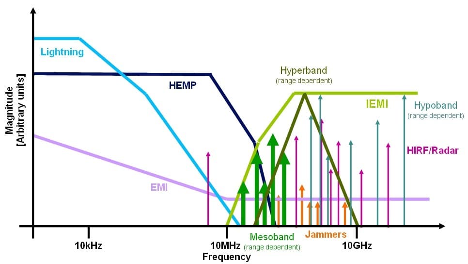
Figure 1
It can be seen that IEMI differs from most other EM threats in that it typically occupies a narrow frequency band, dependent upon which specific malicious source is being used. This contrasts with other threats such as lightning and HEMP (high-altitude EMP), which are very broadband in nature.
The other notable difference is the area of the spectrum occupied: IEMI-radiated threats are almost never below 10MHz, as the coupling efficiency of such a threat would be much reduced. Instead the frequencies used tend to be much higher, to improve the effectiveness and penetration of any attack. The exception to this is for pulses directly injected into power and communications conductors, where lower frequencies are able to travel long distances with minimal attenuation.
Methods of Threat Delivery
The biggest problem with protecting against IEMI is that the sources can vary massively between different aggressors and the way any attack is launched.
IEC 61000-4-36 is the standard for IEMI immunity test methods for equipment and systems and should be considered essential reading for anyone attempting to protect against IEMI. IEC 61000-4-36 defines categories of aggressors as Novice, Skilled and Specialist. These definitions are based on their capability, and IEC 61000-4-36 gives examples of the types of attack one could anticipate from those categories.
Generally Novice attacks will be short-ranged or require some direct access and take the form of technologically very simplistic and low-cost methods such as modified microwave ovens, ESD guns or even EM jammers that can be bought online for a hundred Euros. Although unsophisticated, such attacks should not be underestimated and could easily cause persistent disruption or damage without leaving an evidence trail of an attack. An example of what can be constructed from rudimentary everyday components is shown in Figure 2.

Figure 2
The next category of skilled aggressors comprises those with good understanding and experience or who have access to commercially available equipment. That equipment could be something like the Diehl pulser pictured in Figure 3.
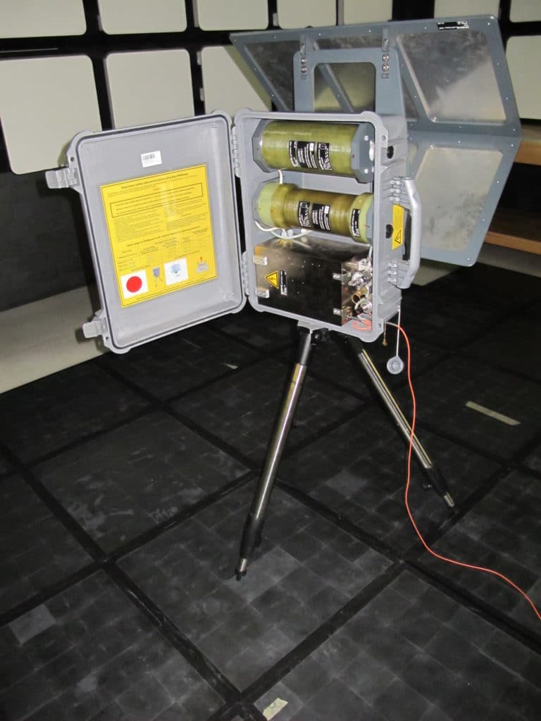
Figure 3
This is an off-the-shelf “interference source” capable of emitting a 350MHz damped sine wave output and 120kV/m at 1m continuously for 30 minutes. With an appropriate antenna, it would be capable of disruption or damage at a greater distance.
In the Novice and Skilled categories one could also anticipate conducted attacks where access is possible, involving direct pulse or continuous wave injection onto the power and/or communication lines. These should not be underestimated and can have huge impact on systems, with effects such as: triggering of safety protection devices or disruption of switched mode PSUs, causing power cuts as well as physical denial of services (DoS) by flooding xDSL or ISDN systems. The ultimate threats are high-power pulses that bring about physical damage to equipment.
The third category of Specialist is in the realms of research laboratories and high-end military programs with accordingly high capabilities. This covers systems such as the Boeing CHAMP missile and the Russian-developed RANETS-E, which is capable of a 500MW output and range of 10km. Plentiful information on both systems is available in the public domain. Although it would be obvious if a large truck with antenna was parked outside, or a missile had been launched overhead, a Specialist aggressor’s equipment can be much more subtle than that, especially if fixed equipment can be set up nearby – in a building across the street or even an adjoining room. This allows complex equipment to be set up and an attack to go unnoticed for a long time, or perhaps not be noticed at all.
This raises the most critical question concerning protection from IEMI – access. Access is in terms of distance either from threat to target in radiated systems, or to incoming power and communications cables for injected conducted disturbances.
Effects on Operations
Numerous papers have been written on the disruptive and damaging effects of IEMI attacks on electronic systems, and covering that in detail is beyond the scope of this paper. Readers are encouraged to review the many papers and presentations on the subject.
What can be said here is that the effects can vary from the very subtle – errors in data streams and microprocessor instruction operation through to system lockups, hard resets and even permanent damage which renders a system beyond repair.
The exact effect of a particular aggressor’s action against a particular system is very case-specific and would require thorough analysis. However there is one general rule that applies, and it may appear obvious: the greater the interference, either as a conducted or radiated disturbance, the more likely effects will be seen and the more severe they will be.
It has been shown many times that a radiated or conducted disturbance will cause damage at higher power levels, but at lower power levels can cause only minor upsets or even no significant effect at all. This makes disturbance attenuation the key to protection.
Asset Protection
While the internal resilience of equipment is a key part of IEMI protection, it is known to vary even between equipment made by the same manufacturer. So often it is not possible to influence that characteristic, especially where third-party equipment is concerned, so one must look instead at how those assets can be protected by external measures.
As can be seen in Figure 1, there is little frequency overlap between traditional threats and IEMI. One should bear this in mind when planning the protection strategy for a system. However it does not mean that existing protection systems or even infrastructure are completely useless, just that they shouldn’t be considered the whole solution.
What one does need to consider is the type of IEMI threat likely to be experienced. For example, it is unlikely that a small company in the UK will suffer an attack from a Boeing CHAMP missile directly overhead, but it’s plausible it could be subject to interference from a malicious individual with some pulse generator plans from the internet. It’s plausible that a company of national significance could be subject to organised terrorists, with whatever equipment and skills their organisation possesses.
Bearing this in mind, there are different strategies one could adopt for protection. The obvious and technically naïve strategy is to assume that, because all equipment must be to the standard of the EMC directive, it is adequately protected. However the various EMC directive immunity tests are all significantly below the levels and frequency that could be experienced during an IEMI attack (V/m against kV/m), and typically EMC directive conducted compliance focuses on the lower bands – where SMPS and similar switching noise problems exist that do not arise at the higher bands where most IEMI threats exist. ESD protection only has limited relevance: as it only mandates no permanent damage, disruption is acceptable.
The second approach is to go to the other extreme and apply the traditional metal box / Faraday cage solution shown in Figure 4, as often seen in high-end military applications and EMC test chambers. This assumes no inherent resilience in any equipment and is the same strategy adopted for MIL-STD 188-125 HEMP (nuclear EMP) protection on critical military infrastructure, where even a minor disruption isn’t tolerable. For IEMI protection applications where that same ‘work-through’ requirement exists, then this really is the only guaranteed solution: one would simply need to ensure that the shield performed up to at least 18GHz and the same for the filters on incoming power and communications lines.
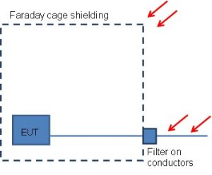
Figure 4
As confirmation of this principle, MPE recently tested their filters against the Diehl pulser pictured in Figure 3 to try out the hypothesis. As shown in Figure 5, the LEDs were positioned both inside and outside the shielded cabinet. At this stage it was only a qualitative test, with the power source outside filtered using one of MPE’s HEMP filters. The effects were very clear, with no LEDs being damaged inside the cabinet even at very short ranges from the Diehl source: however most of the LEDs outside suffered failure at this and greater distances.
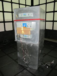
Figure 5
There are plans to do more detailed quantitative tests against this and other IEMI sources, including the often touted modified microwave oven. However, knowing that the same filter construction has been proven in 40GHz filtering / shielding applications and the energy from IEMI is still below that of MIL-STD 188-125 (150kV 2500A conducted), the outcome is expected to again be positive and to show that standard MPE HEMP filters also protect against IEMI. The assessment is likely to take a similar approach to that of HEMP filter testing described in IEC 61000-4-24, where residual currents and voltages are measured on the protected side of the filter against a known incoming pulse.
For lesser applications taking this approach, one would only need adequate shielding and filtering to the appropriate level for the anticipated threat. The reality is that such a shield wouldn’t be worth providing unless it was giving at least an overall 60dB reduction. This approach could be scaled appropriately to what is desired to be protected: if only a server cabinet is deemed critical, then only that needs shielding and filtering. The downside of such protection is the cost – for a cabinet alone, it could run to over £1000.
Protecting a large, high-end military facility can cost in excess of £100,000 in filters and more than £1m in shielding and architectural work, even if done at the point of construction. Retrofit would add even further to the costs. Such a facility would also require significant maintenance, adding to the bill. This cost can be very off-putting for all but the most critical of applications.
Another approach to the problem is to assess what protection is already there, the threats that are likely to be a problem, what really needs protecting, and to apply a staged protection scheme.
This concept doesn’t rely on a single component providing huge signal attenuation, but on multiple smaller and often incidental components to give a similar attenuation at a much reduced cost. The concept is shown in Figure 6. This is a tailored solution to suit individual scenarios and equipment.
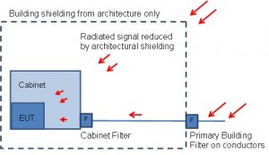
Figure 6
It is here where the EMC directive (and other regulatory EMC standard) immunity tests become useful: they provide a good baseline for building upon with other protection methods. Caution should be exercised here, as there is a danger of “building on sand”. The EU “CE” mark is a self-certification system, meaning that a CE mark is only as trustworthy as the company placing the mark upon the product.
One only has to look at the many analyses of USB phone chargers and LED lighting systems to know that many products do fall far short of the standard (not just for EMC) when put to test. Assuming that the regulatory immunity can be trusted, then a typical attenuation of 60dB might be required from perhaps 10MHz to 1GHz. It becomes less clear above this frequency, as many items of equipment stop testing at 1GHz, and so the base equipment immunity is often unknown above this.
The next asset in the protection scheme also comes for free – the architecture around the system. Several studies have shown that some buildings can provide up to 20dB of shielding, while others provide almost nothing, the difference being due to the materials used and their construction style.
For instance, concrete rebar can give 11dB of shielding, yet wooden buildings would do well to give 4dB. As with all areas of IEMI, details and specifics can make a huge impact, for instance a metal clad building may appear to offer a rudimentary Faraday cage, but if unfiltered conductors are penetrating that cage, its benefit can drop from what would be 30dB to -10dB, creating a stronger field inside the building than outside. In this case applying appropriate filtering would rectify the situation and provide a solid 30dB. Note that these figures are for particular frequencies, and a proper study of the specific case should be done, with measurements taken if necessary.
The distance between a potential aggressor and a protected system should not be underestimated either and could be quite long relative to the wavelengths used in an attack. If the site has an extensive perimeter with security, or only a specific room needs to be protected in a large building or complex, this gives a natural attenuation to any radiated or conducted attack originating off-site.
As an example of the benefits of distance, basic RF theory tells us a 1GHz radiated attack could be attenuated by more than 50dB over just 10m. This is a practical, controlled perimeter distance for many sites, but caution is advised as this simple illustration is based on isotropic antenna gain and should be considered in that context.
Equipment cabinets and cases can also have protective capability. A typical commercial EMC cabinet compared to an unshielded rack could provide a consistent 30dB of attenuation up to1GHz and could still be providing some up to perhaps 5GHz.
The conducted protection should try to coincide with the shielding to avoid bypass coupling and prevent any compromises to the inherent shielding protection. If the building has very good shielding, then a large incoming filter at the entry point would be best. But if shielding is very poor or with potential access issues, then the cabinet or individual equipment must carry the majority of the shielding, and this is where the filtering should be located.
Distributed filtering can be used with several lower performance filters in place of a single high-attenuation filter. Some of those filters could be part of the original equipment, but bear in mind that, although most equipment has incoming power filters, these are often only low frequency for EMC compliance and not really suitable for IEMI protection. Furthermore the combination of filters in the system should cover the entire frequency spectrum of concern. This requires assessment against the probable threats and tolerable disruption: there is a standardised way to define these in the appendices of IEC 61000-4-36.
A vital part of the filtering solution is the surge suppression performance against pulse-type IEMI attacks, which can have very high power content and fast rise times. Those rise times can be in the order of nanoseconds or even picoseconds, billionths or trillionths of a second.
Compare this to the most common type of surge suppression – lightning protectors, typically spark gap or MOV varistor types. These typically only need to operate in the microsecond timescale for lightning: although some of the technologies can operate far faster than this, in practice they don’t when used in lightning applications, due to many factors including installation and connectivity styles. This makes any lightning protection very ineffective against IEMI, except for the very slow conducted pulses, i.e. those already in the lightning area of the frequency spectrum.
This is where the crossover with HEMP is important: the MIL-STD 188-125 E1 pulse also has a fast rise time in the nanosecond scale and energy content far exceeding that of any likely IEMI attack. As the performance won’t suddenly cease at the top of the HEMP spectrum, this means that a MIL-STD HEMP protection device will protect against all but the fastest conducted pulses seen with IEMI threats. Nevertheless MIL-STD HEMP devices, as previously discussed, are expensive and quite likely excessive in all but the most sensitive and critical cases where HEMP protection is also likely to be a concern.
Therefore in most cases what is desired is in effect a lower cost and performance HEMP filter, with performance stretching to at least 18GHz. Fortunately the update of IEC 61000-4-24 is nearing publication. It will define a range of performance criteria for HEMP protection on civilian applications which are based on more relaxed residuals than the MIL-STD (it also includes the MIL-STD as the special case) but are still required to respond to the same nanosecond timescale pulse.
This provides a good basis for specification of IEMI surge suppressors and conductor filtering, as it requires demonstration of all the key attributes – fast pulse response, prevention of shielding bypass and ability to handle the power levels expected during such an attack.
Threat Detection
If the system in question can tolerate interruptions or damage without serious unrecoverable consequences, and the business case is not currently strong enough to invest in protection, there is an intermediate step before protection that is complementary to it even when installed.
This takes the form of detection of any incidents and profiling it in the specific scenario, with an aim to gather evidence for the purposes of the cost/benefit analysis of protection systems – and for logging IEMI attacks or disruptions in order to positively identify threats against system faults. This has the added benefit of logging unintentional EMI effects in the increasingly crowded spectrum.
This approach has only become viable recently thanks to a shift in the philosophy of detection systems. Traditional IEMI monitoring equipment is very large, expensive and complex, requiring highly skilled staff to operate. These can give a full profile of any attack or threat detected, with analysis of the specific source in real time, etc. However the cost and maintenance of such a detection system can approach or exceed that of system protection, making detection a costly intermediate step for general use.
To make logical sense, what is required is a detection system of lower cost and complexity. This differs from the traditional detection approach by simply detecting anything that causes a large enough EM disturbance and logging it in the time domain.
By logging the disturbance in enough detail in the time domain, offline analysis can then be performed as shown in Figure 7, removing the need for complex analysis, and thus cost, within the detector. By keeping the costs low, large sites could deploy multiple detectors, giving a far more detailed view of the threat. Information that this could give to the analyser includes increased accuracy on wave shape and triangulation of the threat source, and attenuation provided by existing buildings, infrastructure or shielding.
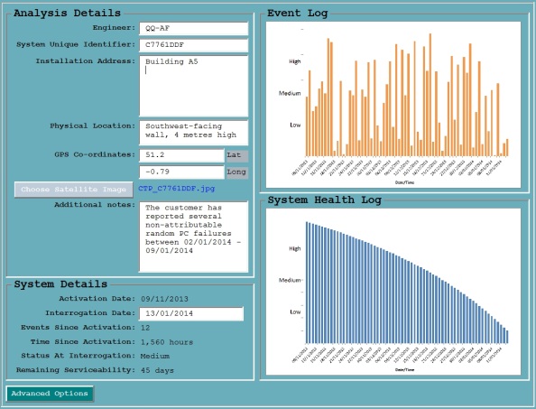
Figure 7
This solution gives the two desired outcomes from detection: an evidence trail for any cost/benefit assessments for stakeholders to invest in protection, and the time-stamping of disturbances, to be correlated with any CCTV or other evidence in legal proceedings.
Summary
It can be seen that the IEMI threat is real regardless of application – whether in security or defence, public or private sector – and that existing protection systems cannot be assumed to be adequate and in most cases will be found wanting by a well-planned attack.
The steps required to effectively and adequately protect against the risk of IEMI are clear – understanding the nature of the threat, taking advantage of existing protection systems and supplementing them with IEMI-specific measures where necessary.
