EMI analysis continues to expand as more companies add electronic control and wireless remote capabilities to their products. The need to drive speed and efficiency throughout the design process means these engineers need to conduct EMI pre-compliance testing on the same bench as the debugging embedded and RF signals. Modern instruments often combine debugging and pre-compliance modes to help engineers save valuable time and resources in their design process. The availability of flexible instrumentation to fit these needs is helping to drive new test trends. To visualize and resolve more issues as early in the design as possible engineers require flexible solutions capable of capturing and visualizing issues across the digital, analog, and RF domains. In addition to traditional EMI pre-compliance scanning new solutions make it possible to capture emissions in real-time, debug EMI in the time domain, and combine these capabilities in the multi-domain analysis.
Real-Time Debugging and Visualization
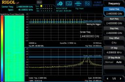
Capturing emissions of interest can be done in a number of ways, but real-time debugging and visualization solutions are gaining popularity because of how easy it is to move between emissions testing and debugging. Real-time visualization makes it simple to directly capture RF emissions in real-time. Without waiting for a scan or potentially missing short-duration emissions, real-time visualization seamlessly captures the spectrum even allowing the engineer to trigger directly on a frequency or power envelope. Visualizing RF signals over time is also simplified with the fast capture and response of a real-time system.
Figure 1 shows how emission detection and debugging are combined in real-time spectrum analysis. With real-time, engineers can trigger on power levels across a spectrum as shown in the bottom panel. The top panel shows the time domain view. This signal is not constant but appears for a short duration about once per millisecond. With this information, engineers can start looking for the likely root cause of this signal when it appears in a design revision. This approach is much more efficient than backtracking from a failed compliance test to find the cause of an issue made more complex over multiple revisions. The left panel in Figure 1 shows a spectrogram view. This shows how the spectrum changes over longer time periods helping engineers determine likely contributors to the emission.
EMI Pre-Compliance in the Time Domain
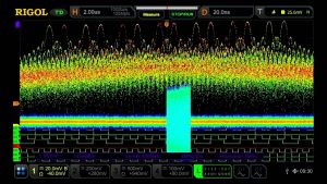
Real-time visualization enables engineers to trigger and isolate emissions as well as helping to determine root cause, but often the underlying issue is a digital or analog signal that requires debugging of multiple signals together. One of the fastest-growing EMI trends lies in using an advanced analysis oscilloscope to debug these emissions directly in the time domain. Modern oscilloscopes have the capability to accurately visualize the frequency content of embedded signals using enhanced FFTs.
Engineers use this ability to visualize the spectrum over time and correlate analog and digital signals as shown in Figure 2. This is an effective method for isolating time-domain signals that might be causing emissions tor are related to bugs. Use the oscilloscope’s FFT to find the frequencies within a signal, locate the source of a problematic signal, and confirm the digital state that leads to the issue. The ability to correlate multiple analog and digital signals, while comparing their RF energy simplifies debugging for these types of signals.
Scanning for Emissions
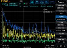
The traditional method of EMI pre-compliance testing includes scanning the broader spectrum looking for signals or problems. This method provides a high-performance scan of the instrument’s entire span making it ideal for capturing unexpected emissions. Using CISPR average and quasi-peak detectors add additional insights to emissions behavior. Most engineers do not have access to a chamber for their normal debugging and product updates. In benchtop debugging, engineers use these swept measurements with a near field probe. This captures emissions near the probe perfect for identifying and locating emission sources and areas of concern in fixtures, enclosures, and cabling. Signals can be captured and compared between versions to identify emissions improvements or issues in the latest revision.
Figure 3 shows a 1 GHz scan using near field probes with multiple trace types. This is a common setup for monitoring emissions while sniffing a board with the probe. This method quickly captures a variety of emissions. Signals of interest captured in this mode can be further evaluated using real-time debugging.
Multi-Domain Analysis
When efficient debugging is needed to resolve EMI challenges, the best approach is to combine real-time and time-domain debugging. This combination of instruments makes it possible for an engineer to capture detailed emissions in real-time and correlate them together with analog and digital signals. Advancements in real-time analysis with available IF output means engineers can now set up triggers for emissions at a frequency or power and immediately view the digital state or embedded analog signals. When needed, trigger on embedded signals and quickly verify the resulting spectrum in real-time. The flexibility of these multi-domain test setups makes it easy to isolate emissions or debug signals within a normal debug workflow for engineers. One of the biggest advantages of this approach is that design changes can be evaluated from multiple perspectives. When engineers make changes that they are concerned may have an emissions impact, the instruments can be set up to trigger on the new state and capture the resulting spectrum. When engineers find an emission they can easily synchronize the RF content with the correct state data to determine which design changes may have exacerbated the issue.
EMI Mode Verification
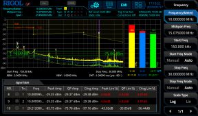
Pre-compliance measurements are ultimately about being confident about your design when it’s time to send the product out for final compliance testing. The ability to capture emissions and design problems in real-time and then debug them helps reduce wasted effort and rework. In order to capture everything that might be found in a compliance, test requires dedicated EMI capabilities. Even without a fully compliant test chamber, EMI measurements can closely match those from a lab. This EMI mode verification requires multiple simultaneous detectors, limit line evaluation, final test verification, and segment definition. Some instruments include a dedicated EMI mode to facilitate this analysis. The EMI mode shown in Figure 4 combines all of these capabilities into an instrument test solution. One of the key advantages to this test methodology is the ability to quickly verify emissions found during a segment scan against multiple detectors and limits. With the correct test setup, this analysis helps engineers stay focused on emissions or signals that are likely big enough to cause compliance issues, while allowing them to ignore emissions that won’t impact the final compliance test.
EMI pre-compliance measurements provide important feedback to engineers throughout the design process. Visualizing and debugging emissions and their root causes is a challenging and time-consuming task for any engineering organization. The emergence of flexible real-time spectrum and time-domain analysis for multi-domain debugging enables engineers to quickly discover issues and solve complex problems on their bench. With a modern oscilloscope and a real-time spectrum analyzer working together, these test techniques provide a flexible set of debugging capabilities that empower engineers to solve problems faster and more efficiently. Getting products to market faster by enabling real-time debugging and building confidence in the design as a project moves into final EMI compliance testing. These debugging modes offer a complete set of EMI pre-compliance capabilities throughout the design process from the first hardware to the final release. Engineers can now access all these capabilities in a pair of instruments that work together to visualize and debug a wide variety of embedded issues.
