Mart Coenen
EMCMCC
[email protected]
Mechatronics means: mechanics combined with electronics. The amount of electronics involved in mechatronic systems is constantly increasing. The required precision, speed and stability of mechatronic systems is co-determined by the reliability of all kind of sensors with electronics, embedded controllers and pulse width modulated (PWM) motion drives with increasing performance and bandwidth.
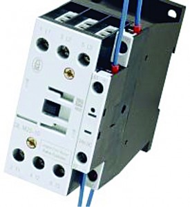
Figure 1 – Example of an electronically driven power relay
To ensure a correct and safe operation of the electronics involved, parameters like: power integrity (PI), signal integrity (SI) and electromagnetic compatibility (EMC) need to be addressed. When building modular mechatronic designs, ‘inter-system’ EMC is usually specified but PI and SI are normally ignored as explicit requirements fail. However, when building modular mechatronic sub-systems, intra-system PI, SI and EMC requirements have to be met to ensure reliable operation at the required performance level.
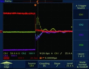
When mechatronic systems are built in such a way that their AC or DC supplies are situated far away from their loads, PI and SI will be affected quite easily. An example is the on-switching of ‘green’ (energy efficient) electronically driven power relays (see figure 1), which draws an instant current of tens of amps over tens of microseconds, (see figure 2). Though the charge required
(Q = òI(t)dt) is limited, the local supply will collapse shortly due to a voltage drop over the wire inductance: L·di/dt.
Figure 2 – Peak start-up current of electronic driven power relay (yellow curve)
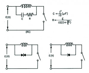
To sustain the relay in its closed position, a hold current of just a few tens to a hundred mA is drawn and less energy is consumed. Operationally, the relay contacts are switched much faster (thus resulting in less arcing on the contacts) but leading to much higher voltage and current transients: dV/dt or di/dt’s, at the load side [1, 2]. With conventional electro-mechanical relays, the current through the relay coil inductance builds up smoothly when it is connected to its supply. A freewheel diode, transient voltage suppressor (TVS) or snubber (RC-network) is used to clamp the coil’s reverse voltage when switched off, see figure 3. Similar measures are also applied inside the electronic driven power relays. Mechatronic relays are used over solid-state relays as they can handle higher currents and they suit electrical safety with respect to the required insulation over open contacts.
Figure 3 – Different voltage clamping techniques.
Instant transients occurring on an AC distribution system couple onto the DC distribution network which supplies: active sensors, embedded controllers and motion drives. Depending on the AC/DC converter(s) used for supplying these active sensors, the noise suppression i.e. attenuation from AC-input to DC-output is unspecified by the AC/DC converter supplier (as there is no international standard describing the required test methods and its requirements yet). With most electrical safety Class II (= double or reinforced insulated without PE connection) AC/DC converters or poorly grounded Class I converters (= basic insulation withPE connection), these transients are nearly 1:1 coupled from the AC input onto the DC output, due to the internal filtering components used (necessary to satisfy inter-system compliance of the converter itself). From well-designed AC/DC converters, either Class I or II, an RF attenuation of 60 dB (a factor of 1000) or more between input and output can be expected. But even in these design cases, transients of 1000 Volt on the AC-mains are still passed onto the DC-output at a level of 1 Volt. In accordance with the specification of an AC/DC converter manufacturer only an AC ripple in the order of 10 – 200 mV is specified [7], when measured in a 20 MHz bandwidth. Voltages and currents measurements with less bandwidth won’t show these transients at all.
Figure 4 – Example of voltages occurring on a PWM driven motor, measured against PE using an external 1:100 differential probe [9].
When a sensor system gets these 1 Volt transients on its supply, differentially or in common-mode, it will be determined by the power supply rejection ratio (PSRR) and the inner front-end design of the sensor (where often mV’s or less are obtained from a physical transducer, which requires 106 – 109 (120 – 180 dB) or more attenuation from signals occurring elsewhere in the system) how it will react. If it is a single switching event, filtering by hardware and/or software can help to suppress the false data that is coming out of the sensor system. When using PWM driven applications, either at low-voltage DC or driven from the AC mains level, the resulting noise induced on the low voltage DC supply distribution network will be repetitive, see figure 4. When non-shielded or falsely applied shielded cables are partly routed in the same cable trays, the induced voltages will be higher. At the motor i.e. load side, often non-filtered PWM switching voltages and currents occur. With a single phase AC-supplied PWM drive system, the internal DC-bus voltage becomes 360 Volt and the peak-peak voltage at the load may exceed 1000 Volt by cable reflections occurring, see figure 4. These repetitive PWM signals also couple onto the rotor shaft, rotating in its grease insulated bearings, which then couples into the encoder. One of the mechanical aspects of these high voltage transients occurring is bearing corrosion due to arcing through the grease film in the bearings, see figure 5.
The impact of transients on sensor systems may occur twofold:
- either communication gets corrupted. Unintended index pulses on I/Q-sensor signaling occur (by which the system loses its reference position) or
- the sensitivity of the sensor (in particular with high input impedance front-ends) goes down by some orders of magnitude such that e.g. distance measurement resolution derates from sub-nanometer to micrometers or even millimeter.
The coupling from cables onto other cables is determined by the electrical and magnetic fields stemming from these cables. Solutions to reduce coupling can serve both ways, as cables are passive networks and as such reciprocal. When the sum of all signal currents are confined to the inner wires of a shielded cable, the resulting external magnetic fields will be low. Fulfillment of this condition can be easily measured as the common-mode current on the inner wires of such cables as a whole will be ‘zero’. Electric fields can easily be minimized by connecting the cable’s (inner) shield to the reference terminal belonging with the circuit, which often is not the ground or protective earth (PE) terminal of the (sub-)system’s enclosure.
Figure 5 – Example of bearing corrosion as a result of transient arcing
Outer cable screens shall be electrically connected through their connector shells to the enclosures connected to. This electrical connectivity is determined by the various surface treatment of the metals used. Powder coatings, anodized aluminum, commonly used from a mechanical and/or an esthetic point of view, are providing one of the best electrical insulators. Using stainless steel threat inserts, which are glued into an aluminum frame, extends this non-conductivity.
Figure 6 – Summary of observed LF differential voltages on mains wires in industrial installations (excerpt from a working group document IEC 22/199/cd)
The industrial mains disturbance levels given in figure 6 reveal that power line communication (PLC) [1] needs to use higher signal levels (to enable communication) than those resulting from industrial systems [3] (solid green line). The active infeed converters (AIC), used with windmills and photovoltaic systems to convert the harvested energy onto the mains distribution system, exceed these disturbance levels even further [11 – 16].
Most, if not all, AC/DC, DC/AC and AC/AC converters and PWM motion drive systems are switching in the frequency range of 2 – 150 kHz as being a free zone for RF emission in EMC legislation. Most active inductive or capacitive sensors operate in the same frequency domain, also to avoid any formal legislative EMC immunity requirements. Even temperature and strain gauge sensors have a front-end sensor bandwidth over 20 kHz and often suffer intra-system immunity issues, though being inter-system EMC compliant. The likelihood in having unintended interaction in a modular mechatronic system design is increasing progressively. Unintended coupling may occur through: air (E/H-fields), via mechanical frames (common-impedances) or result from cables running in parallel (crosstalk) which can’t be resolved by simply adding an opto-coupler somewhere along the signal path. It is unpleasant when your car’s motor management system doesn’t recognize the contactless key anymore when the roof of your convertible is closing while driving.
All this requires an extended conceptual approach, with additional specifications, to anticipate to such interaction by ‘selection’ and/or ‘design’, A CE-mark on a sensor system or PWM drive product doesn’t add anything to the avoidance of intra-system issues. These considerations shall be extended beyond the boundaries of the sub-system, in particular when the sub-system is part of an even larger system which adds additional constraints (and should be made clear to all parties/suppliers involved).
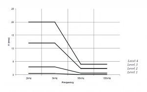
Figure 7 – Proposed LF immunity requirements to conducted, differential mode disturbances in the frequency range from 2 – 150 kHz to be superimposed on the mains voltage at AC mains ports [7].
International standardization, work is progressing to close the non-regulated gap between 2 and 150 kHz. The mains harmonic disturbances up to 2 kHz are legally covered [5] (up to 16 A/phase) and up to 75 A/phase [6]. Recently, an inventory document has been written with respect to the many signals that appear most severely in this frequency band, see figure 6 [4]. In parallel, work is already progressing in CENELEC’s sub-committee 205 and IEC TC77A by writing new proposals on how to perform and apply immunity tests uniformly, see figure 7 [8, 9, 10]. The levels are taken again with some margin over those given in figure 6. Care shall however be taken with these out coming documents as again only inter-system issues are being addressed while intra-system effects are being ignored and left over to the modular mechatronic system designers. To enable modular mechatronic system design, unified intra-system PI, SI and EMC requirements shall be defined to reduce time-to-market at limited costs.
References in systematic order
[1] EN 50065, Signalling on low-voltage electrical installations in the frequency range 3 kHz to 148,5 kHz. General requirements, frequency bands and electromagnetic disturbances, 2011, CENELEC, www.cenelec.eu
[2] EN 50160, Voltage characteristics of electricity supplied by public distribution networks, 2010, CENELEC, www.cenelec.eu
[3] EN 55011/ IEC CISPR 11, Industrial, scientific and medical (ISM) radio-frequency Equipment Electromagnetic disturbance characteristics. Limits and methods of measurement, 2007, CENELEC, www.cenelec.eu or 2009, webstore.iec.ch
[4] IEC 61000-2-5, Electromagnetic compatibility (EMC): Environment – Description and classification of electromagnetic environments, 2011, webstore.iec.ch
[5] IEC 61000-3-2, Electromagnetic compatibility (EMC): Limits – Limits for harmonic current emissions (equipment input current ≤ 16 A per phase), 2005, webstore.iec.ch
[6] IEC 61000-3-12, Electromagnetic compatibility (EMC): Limits – Limits for harmonic currents produced by equipment connected to public low-voltage systems with input current > 16 A and ≤ 75 A per phase, 2011, webstore.iec.ch
[7] IEC 61000-4-13, Electromagnetic compatibility (EMC): Testing and measurement techniques – Harmonics and interharmonics including mains signalling at a.c. power port, low frequency immunity tests, 2009, webstore.iec.ch
[8] IEC 61000-4-16, Electromagnetic compatibility (EMC): Testing and measurement techniques – Test for immunity to conducted, common mode disturbances in the frequency range 0 Hz to 150 kHz, 2011, webstore.iec.ch
[9] IEC 61000-4-17, Electromagnetic compatibility (EMC): Testing and measurement techniques – Ripple on d.c. input power port immunity test, 2009, webstore.iec.ch
[10] IEC 61000-4-19, Electromagnetic Compatibility (EMC): Testing and measurement techniques – Test for immunity to conducted, differential mode disturbances in the frequency range from 2 kHz to 150 kHz, at a.c. ports, 2012, committee draft, webstore.iec.ch
[11] IEC 61800-3, Adjustable speed electrical power drive systems – Part 3: EMC product standard including specific test methods, 2004, webstore.iec.ch
[12] IEC 61800-5-1, Adjustable speed electrical power drive systems – Part 5-1: Safety requirements -electrical, thermal and energy, 2007, webstore.iec.ch
[13] IEC 62040-1, Uninterruptible power systems (UPS) – Part 1: General and safety requirements for UPS, 2008, webstore.iec.ch
[15] IEC 62040-2, Uninterruptible power systems (UPS) – Part 2: Electromagnetic compatibility (EMC) requirements, 2005, webstore.iec.ch
[16] IEC 62103, Electronic equipment for use in power installations, 2003, webstore.iec.ch
Mart Coenen (BSc ’79) has had over 33 years of experience in EMC in various fields and has published books, national and international papers and publications. He has been actively involved in international EMC standardization since 1988 and is the former project leader of standards IEC 61000-4-6 (Immunity to conducted disturbances induced by radio-frequency fields) and IEC 61000-4-2 (Electrostatic discharge immunity test); he later moved his focus towards EMC in integrated circuits.
Mr. Coenen has been the convener of IEC TC47A/WG9 and a member of WG2, for which he was given the IEC 1906 award in 2006, after publishing various parts of the IEC 61967-x, IEC 62132-x and IEC 62215-x series. He is a co-founder of the Dutch EMC/ESD Society and has been a part-time lecturer at post-academic EMC courses for the last 27 years. Mr. Coenen has owned his private consulting company EMCMCC since 1994, where he focuses on PI, SI, EMC and system integration issues in e-hardware.


