Candace Suriano
Suriano Solutions
John Suriano
Nidec Automotive Motors Americas
PART 1: MY CELL PHONE CAN TALK TO ME IN STEREO
Dear John,
I am snowed in here at home with the kids. You may be in an EMC lab solving some tough issues, but I’ve been very busy here at home with some interesting problems of my own. We’ve been bothered by the behavior of our computer speakers. Periodically my cell phone I keep on the shelf talks to me on the computer speakers about 8 feet away. No, it doesn’t use words that I can understand; instead it talks in some pulsed sort of buzzing noise that reminds me of Morse code.
Yes, I’m still using my “stupid” phone; I know you want me to switch to a smartphone. It’s a GSM phone operating at 1.9GHz. I have done some simple tests that led me to some remarkable conclusions. I think they nicely illustrate some of the fundamental principles of EMC.
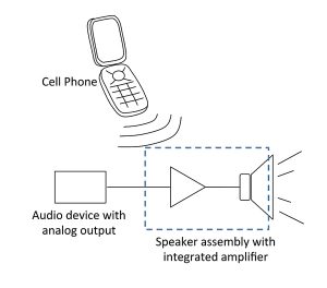
First I made some basic observations. The phone makes a noise on the speaker periodically. I held the phone up to the speakers, made a call and sent a text with the phone (see Figure 1). Both actions resulted in the noise. I concluded that the noise is not related to the ringer or the vibrator in the phone.
Every so often the cell phone sends a signal to let the network know where it is located. So I know that the cell phone was just calling its home (not ours), when it makes the periodic noise. There doesn’t appear to be much difference in the interference when it was calling its home or making a normal call.


The signal from the phone is transmitted in bursts. The repetition rate of the bursts is on the order of milliseconds as shown in Figure 2. Each burst contains 1.9GHz modulated waves. The information is encoded in phase modulation. A spectrum analyzer set to zero span at 1.9GHz would show the burst signals as a pulsed waveform as shown in Figure 3.

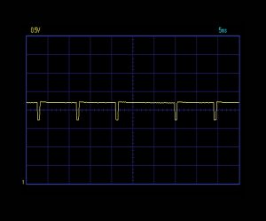
Then I stole/borrowed our daughter Frances’ speakers from her (Figure 4) to find out if they also had a susceptibility to the cell phone signal. The noise was also on these speakers. I started to probe her speaker circuit board with my old Velleman PC scope. Figure 5 is the signal I saw measured at one of the output pins of the speaker driver IC while the cell phone was communicating. The speaker IC is a commercially available stereo amplifier comprised of cascaded operational amplifiers.
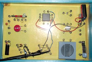
One of the primary building blocks of an operational amplifier is the emitter follower circuit. A typical emitter follower circuit is shown in Figure 6. I wondered if this simple circuit is influenced by the cell phone. How else to do this but I did it with our old 20 in 1 Electronic Project Kit shown in Figure 7. With the cell phone nearby to the circuit, the emitter follower circuit did indeed pick up the noise.


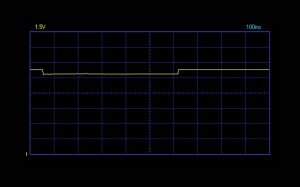
The voltage at the emitter from the cell phone is seen in Figure 8. It seems like the emitter follower circuit is susceptible to the signal my old phone puts out, just like the speaker circuit. This is actually an example of a basic susceptibility problem. An RF signal from an intentional or unintentional radiator can produce a DC voltage in a transistor circuit. The cell phone sends out bursts of 1.9GHz signals. Every time a transmission is made by the phone it causes an offset in the voltage output of the transistor. This means the speaker electronics act as an envelope detection circuit for the cell phone output. Since the repetition rate of the communication bursts is in on the order of milliseconds, the voltage offsets from the transmission results in audible frequency noise in the amplifier circuit. Thus, the noise is in the audible range because the speaker electronics are picking up the pauses between the bursts of data.
A longer continuous wave signal produces a longer offset of the voltage output. I tried the same experiment with one of our handheld mobile radio transmitters instead of the cell phone. Figure 9 shows how the voltage offset is present when the radio transmit key is depressed. Therefore the speaker electronics still couple into the emitter follower circuit, but not in the audible range.
Clearly RF transmissions can cause excitement and problems in all sorts of electronic equipment. An RF signal can result in a DC voltage in transistor circuits affecting the operation of the equipment. This is why susceptibility tests include various tests of immersion in RF fields. As shown in Figure 10, the cell phone can induce RF current in the transistor circuit. The RF current is rectified by the transistor and a DC voltage drop is produced between the base and collector. This alters the bias of the transistor and results in lower output voltage of the circuit.
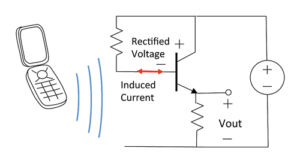
This is very disconcerting to me. I can’t imagine how pervasive this problem could be. No wonder they don’t like cell phones in hospitals and airplanes! It’s a good thing that a lot of electrical equipment is tested for radiated susceptibility.
I am planning to keep my old cell phone, but I want to get rid of this annoying noise from our household speakers! I first used foil to shield the phone from the speaker and speaker signal wire. When the speaker and speaker signal wire was shielded from the signal, the speaker did not emit noise. If I put a piece of foil behind or around the phone, there is a shield and the phone does not couple into the speaker’s electronics. However, this is not a great way to shield the phone because our children do not want to hang around a mom with a shinny foil covered phone. The kids’ new smartphones do not cause the speakers to emit an audible noise. Part of their silence is because they use the wireless in the house when they make their calls. However, when they disabled the wireless communication they still did not couple into the emitter follower circuit audibly. This is because their phones do not transmit in bursts like the older phones. When I watched their smart phones’ transmission on the scope, their phones transmitted in an initial burst and then continuously. Perhaps that transmission waveform is because they are 4G. They may generate a DC offset in the amplifier that is not pulsed.
Well that’s enough for now. I included some helpful references for you at the end of the letter. Don’t forget to write.
Love,
Candace
REFERENCES
[1] Paul Horowitz and Winfield Hill, The Art of Electronics, Cambridge University Press, New York, 1980.
[2] Victor Grinich and Horace Jackson, Introduction to Integrated Circuits, McGraw Hill, U.S.A., 1975.
ABOUT THE AUTHORS
Candace Suriano is a graduate of GMI Engineering & Management Institute (BSME) and has graduate degrees from Purdue University (MSME, MSE) and the University of Dayton (Ph.D.). She is the author of numerous papers and articles on electromagnetic compatibility and chaired an antennas and probes workshop at several IEEE EMC symposia. Candace is currently working to encourage young people to explore electrical engineering by organizing Library Kit donations and demonstrations by groups from the Southeastern Michigan IEEE. Her interests are in the areas of electromagnetic compatibility and electromagnetic modeling. Candace is a mom with interests in MOM.
John Suriano is a graduate of GMI Engineering & Management Institute (BSEE) and has graduate degrees from Purdue University (MSME, Ph.D.). John is the author of numerous papers and articles on electromagnetic compatibility and motor design. He supervises an EMC laboratory for Nidec Automotive Motor Americas in Auburn Hills, Michigan. He has interests in electric motors and electromagnetic modeling.


