Candace Suriano
Suriano Solutions
John Suriano
Nidec Automotive Motors Americas
Dear John,
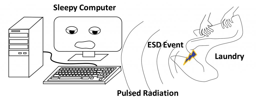
Once again it’s a cold dry winter here and I have found that there is a great way to keep warm— by doing the laundry. I discovered something really strange, though: when I’m taking the laundry out of the dryer it sometimes wakes up the computer on the desk almost ten feet away! I knew I wasn’t going stir-crazy during the long winter because I saw it several times. I figured the computer just couldn’t get any sleep during the electrostatic lightning storms generated by the laundry. What a great opportunity to use some of our old EMC demo equipment with the kids to actually solve a problem…
As you know, the desktop computer in the laundry room is about ten feet away from the dryer. I found that when I removed some freshly dried fuzzy fabric from the dryer, the PC would suddenly wake up as shown in Figure 1. The fabric produces a particularly nasty electrostatic discharge (ESD). The discharge is actually a very fast conduction of charge through gas plasma between parts of the fabric having opposite charge polarity [1]. The duration of the arc is fractions of a microsecond [2] and so produces a very short pulse of radiation which propagates across the laundry room to the computer.
This is, of course, a great opportunity for diagnostics and problem solving:
1.) Use a reliable method for generating ESD
2.) Find the responsible component for causing the problem
3.) Define a repeatable test setup
4.) Realize solutions
5.) Explain the results
The reliable test method
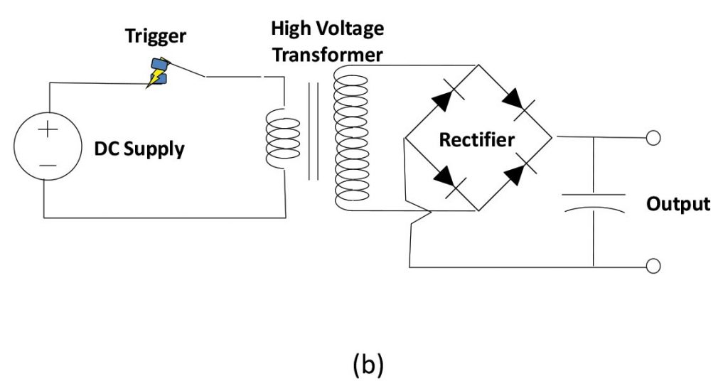
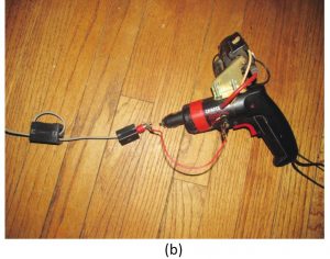
ESD is somewhat random when it is generated by fabric. A more predictable result can be obtained using our home-made ESD gun shown in Figure 2. The gun uses a principle similar to that found in a mechanical car ignition. A trigger on a screw gun is used to interrupt DC current to the primary coil on a high voltage transformer from a TV. The secondary voltage is rectified and used to charge capacitors on the output. With one click of the trigger the gun can generate enough voltage for a spark at the output. Additional clicks make a bigger spark.

The responsible component
It was actually quite easy to find the component responsible for the computer malfunction. First, it was observed that making an arc with the ESD gun nearby to the computer could reliably awaken it from sleep mode. Since the keyboard is the normal user interface for this function it was the primary suspect. When unplugged it was found that the ESD gun could not wake up the computer unless it was nearly contacting the mouse.
The keyboard is a USB device. USB has differential data lines D+ and D- which transmit the information from the keyboard to the computer. The other two wires in the cable are positive and negative DC power. A USB jumper cable was placed between the keyboard and the computer. The jumper cable was opened up so that our PC oscilloscope could be used to examine the signals on these lines. Note that the measurements with the oscilloscope probes display 1/10 the actual voltage due to probe attenuation. Normal communications are shown in Figure 3(a) when the computer is awake. When the computer is asleep and a key is pressed there is a signal of almost 900mS from the keyboard as shown in Figure 3(b).

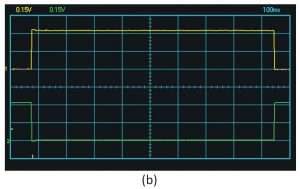
Figure 3. USB communication (a) normal awake data communication, (b) ~900mS pulse when awakening
The same setup was used to see the signals during an ESD event. The oscilloscope trigger picked up the ESD event as shown in Figure 4(a). However, this transient voltage on D+ and D- is not what wakes up the computer. The computer is waiting for a 900mS pulse. By widening the time scale it is apparent that the ESD event causes the keyboard circuit to produce a normal wake pulse as shown in Figure 4(b). There is more than 5mS between the ESD event and the response of the circuit which wakes up the computer. The ESD causes the computer to wake up, but the same ESD signal does not cause spurious characters when the computer is awake.


The repeatable test setup
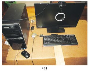
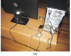
In order to have some confidence in the test results a repeatable setup of the computer and keyboard was constructed as shown in Figure 5(a). Guidelines showing the placement of the keyboard and the keyboard cable were drawn on the cardboard. The cardboard also helped protect our nice coffee table from the pursuit of scientific inquiry. A 1”X4” board was used as a guide to apply ESD discharges at known distance and orientation to the equipment as shown in Figure 5(b).
Instrumentation was also added. A loop antenna was made from the rim of a cottage cheese lid and some wire. That old Captain Nemo-like current probe we constructed from candlestick holders and Fari-rite p/n 5943003801 [3] also came in handy to measure the common mode current on the keyboard cable.

With this test setup the ESD gun has to be moved at least 18” away from the keyboard to prevent the computer from waking up on the lowest ESD setting (1 click of the trigger). The loop antenna measurement (in green) and current probe measurement (in yellow) for this condition are shown in Figure 6. The loop voltage, more than 2V (remembering that the scale for this is 1/10), is quite substantial.

Since we made 2 of the candlestick current probes, one of them was used as a common mode injection probe as shown in Figure 7(a) after the manner of ISO 1152-4:2011 [4]. In the standard method the injected signal is from a signal generator. However in this implementation the signal source is the ESD gun as shown in Figure 7(b). In order to limit the injection current a resistor was used in the pulse return cable. Also it was discovered that the computer could be awakened by the probe even when the probe was not clamped around the keyboard cable due to common mode current on the probe feed cable. To fix this problem ferrite beads were added to the probe feed cable at the ESD gun injection point as shown in Figure 7(b).
The injection probe was able to easily turn on the computer even with about 1.5kΩ in series with the ESD gun return line. The measurement of the common mode current and the loop antenna voltage are shown in Figure 8(a). The loop antenna is either picking up signal from the common mode radiation off of the keyboard cable or is picking up the pulse from the gun as it injects.
The Realized solutions
Since it is apparent that common mode current on the keyboard cable is able to turn on the computer, common mode suppression was added to the keyboard cable at the keyboard. With this suppression in place the common mode current is reduced and the computer is not awakened by the injection current from the ESD gun. Even with no resistance added to the ESD gun return wire the computer is not booted. The reduced current is shown in Figure 8(b).


Common mode suppression used for the keyboard cable was comprised of a snap on bead from Radio Shack and a torroid with three turns of the cable as shown in Figure 9(a). The torroid is Fair-Rite part number 2643804502. It was found necessary to add the turns to the torroid for sufficient reduction of the common mode current.
Next the keyboard was disassembled to understand the path for common mode current and the means by which it causes the wake-up pulse. Surprise! When the keys were removed a common mode choke was discovered on the cable at the controller board as shown in Figure 9(b).


In addition to the beads, a shielding experiment was conducted. A sheet of aluminum foil was placed over the top of the keyboard. This foil was very effective in preventing ESD initiated wakeups. When the foil was placed underneath the keyboard as shown in Figure 10 similar results were observed.

The effectiveness of the solutions is judged by resistance to ESD voltage magnitude (the number of ESD trigger clicks) and the distance from its application. A summary of the effectiveness of the two solutions is given in Table 1.
Table 1. Effectiveness of solutions

The Results Explained
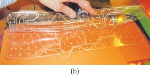
Inside the keyboard is a keyboard controller printed circuit board (PCB) attached to two plastic sheets with printed conductive traces as shown in Figure 11(a). The sheets overlay each other as shown in Figure 11(b). The sheets are “Row” or “Column” contacts based on the array method of ascertaining the connection of a given key. When a key is pressed a conductive dot on the top trace is made to contact a conductive dot on the bottom trace. These traces are the antennas for the ESD pulse radiation which create the common mode current.

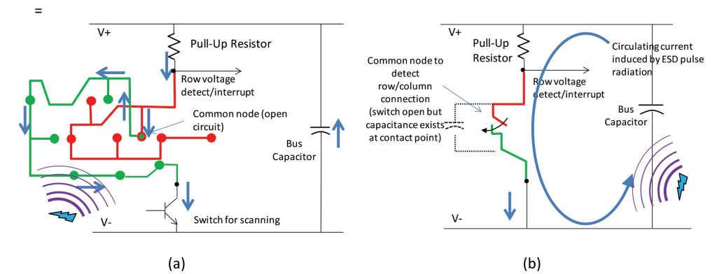
Insight into the operation of a keyboard controller is found in datasheet [5] and the means of monitoring the signal during sleep mode is found in application note [6] for a keypad. One means of accomplishing this is shown in Figure 11. The keyboard has a set of contacts known as the “Row” contacts on the upper sheet and a second set of “Column” contacts on the lower sheet. Each trace on the, row sheet has a contact point which is coincident with one dot on one trace on the column sheet. Pressure from the key causes electrical contact between the two dots. During normal keyboard operation, the controller sequentially turns on the transistor on each column circuit during a scan operation. When the transistor is turned on for the column circuit for the depressed key, the voltage on the row circuit will drop low since it is connected to the minus voltage supply through the connected dots. If the controller finds a low voltage on the row circuit during the scan, it can identify the key responsible for the row/column connection. The circuit is simplified in Figure 11(b). In sleep mode the circuits are not scanned, but rather the transistors of all the column circuits are turned on simultaneously and a low voltage on any of the row circuits causes an interrupt of the controller resulting in the wake up of the computer.
An ESD event is very rapid compared to a normal keystroke. As mentioned, with the computer awake the ESD does not result in spurious characters. The controller de-bounces normal keystrokes during the scanning but this is not the case when asleep since the row voltages are directed to the controller interrupt.

When common mode current is injected in the keyboard cable either by the injection probe or by the radiated ESD pulse from the gun, it passes into the keyboard onto the conductive sheets. The sheets couple back to the cable and to ground by parasitic capacitance as shown in Figure 12. The current passing through the pull-up resistors results in a voltage drop that can be seen as low voltage on the row circuit even if no key is pressed. This triggers the controller interrupt and subsequently the wake-up pulse as in Figure 4(b). Placing beads and toroid on the cable reduce the common mode current and the susceptibility to the ESD.
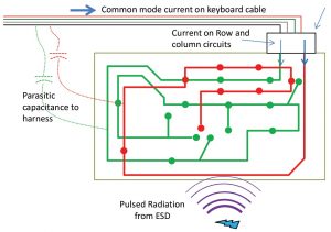
This explanation, however, is not consistent with the effectiveness of the aluminum foil. The foil should improve the common mode coupling to the keyboard and make it more sensitive to the ESD pulses. A closer examination of the circuit leads to a reasonable explanation. In the circuit a bus capacitance across the supply voltage lines would result in a circuit loop with the row and column traces as shown in Figure 13(a). The circuit is connected not only by the bus capacitance but also by capacitance between the conductor dots at the common point of a given row and column trace as shown in the simplified circuit of Figure 13(b). When ESD pulse radiation passes through the loop it causes a voltage drop on the pull-up resistor.
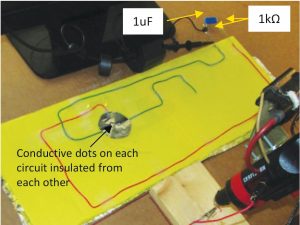
Radiation from an ESD event also causes circulating currents in a piece of foil underneath the keyboard. The current is directed to produce a field which opposes the field hitting it from the ESD radiation. This reduces the field levels nearby to the foil surface and thus should reduce the circulating current in the keyboard. Since it was difficult to test this directly in the keyboard, a simulated keyboard artifact was constructed as shown in Figure 14. The artifact uses two wire segments to represent a pair of row and column circuits. At a common point representative overlaid conductive “dots” were made using conductive tape. A “dot” was placed on each circuit but the “dots” were insulated from one another. The “dots” were made larger than real life to aid in evaluation of the concept. Each circuit was connected by a 1kΩ resistor (for pull-up) to a 1uF “bus” capacitor.
Measurement of the voltage across one of the resistors confirms the theory. Figure 15(a) shows the voltage during an ESD pulse generated at 3” from the keyboard artifact without foil underneath. Figure 15(b) shows a dramatic reduction in the voltage when foil is placed under the keyboard.

So now with some simple common mode chokes and a piece of foil I can safely fold the laundry and our computer can get a good night’s rest.
References
[1] Henry W. Ott, Noise Reduction Techniques in Electronic Systems, 2nd Edition, John Wiley & Sons, U.S.A., 1988, pg. 203.
[2] Henry W. Ott, Electromagnetic Compatibility Engineering, John Wiley & Sons, Inc., New Jersey, 2009, pg. 588.
[3] Candace Suriano and John Suriano, “EMC means more than Everyone Must Comply,” Conformity, Vol. 10, No. 10, October 2005, pp. 12-21.
[4] ISO 11452-4:2011Road vehicles — Component test methods for electrical disturbances from narrowband radiated electromagnetic energy — Part 4: Harness excitation methods
[5] Sprintek Corporation, SK5100/SK5101 FlexMatrix Keyboard Controller, Datasheet, Document No. DS0002 Ver. 1.05, October 2010.
[6] Atmel Corp., AVR243: Matrix Keyboard Decoder, Application Note, Rev. 2532A-AVR-01/03, 2003.


