Explosive growth in technologies like portable electronics, Internet of Things (IoT) devices, and autonomous vehicles has led to a world full of electromagnetic interference. Efficient EMC testing is more critical than ever, and is dependent on high-quality test equipment. Historically, not a lot of education has been provided on the careful considerations needed for determining and selecting the proper quality test equipment demanded for this testing. This paper walks through the important considerations for selecting test equipment, specifically for EMC testing.
Introduction
Electromagnetic compatibility (EMC) testing has been around for decades and will continue as long as there are electronic devices in use. What has become apparent, is that the need for EMC testing has continued to grow nearly exponentially throughout its existence. Test environments and requirements across all industries continue to evolve at a rapid pace. While this rapid growth certainly drives the need for new and additional test equipment to accommodate new requirements, the growth also drives the need for educated and experienced EMC engineers and test personnel.
The problem is that this growth tends to outpace available EMC resources. It is not uncommon to see engineers and technicians with little or no EMC test experience thrust into positions that even a seasoned EMC engineer could have difficulty with. Again, formal EMC education is not always readily available to some organizations and test programs often don’t have the available time for someone to get up to speed. That said, this paper is intended to examine the thought process behind selecting and sizing appropriate test equipment when the need arises. There are numerous types of EMC testing, which require numerous types of test equipment. Significant amounts of time could be spent on each one of these tests, but in the interest of brevity, we will focus the efforts of this paper on radiated immunity (RI) and RF conducted immunity (CI).
Defining Test Requirements
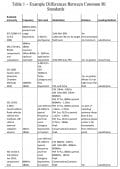
The first step in selecting the proper equipment for RI and CI testing is to understand the requirements of the test itself. Across all industries, RI and CI testing share a lot of commonalities. However, when you dive into the respective test standards, you begin to realize that there are, in fact, some significant differences. An example of these differences for RI can be seen in Table 1. This table is not intended to be comprehensive; however, it does identify some of the key differences between some of the more common test standards in today’s electronics marketplace.
To the uninitiated, some of these differences may not seem that drastic. For example, looking at the cost of an amplifier needed for 200 V/m testing at a 1 meter test distance versus the cost of an amplifier for 200 V/m testing at 2 meters, one might change their mind. Another example involves required modulations. Sizing equipment for a 10 V/m MIL-STD-461 RS103 system may not be sufficient to use for a 10 V/m IEC 61000-4-3 system. The reason is that IEC 61000-4-3 requires a 1 kHz, 80% amplitude modulated signal. This type of modulation increases the overall amplitude of the signal, if not adjusted as in the case of other standards. Therefore, this test would need to be calibrated at 18 V/m, rather than just 10 V/m. This brings up another key difference between these two test standards. IEC uses what’s termed a ‘substitution method’ of testing, where the intended field must be calibrated prior to running a test. In this case, field probes are not used during test. Conversely, MIL-STD-461 allows the use of field probes to actively measure the field during testing, negating the need for calibration.
Again, these are examples and the list could go on and on. The important takeaway here is to ensure that the test requirements are fully realized and understood prior to investigating test equipment. Purchasing the wrong test equipment can prove to be a costly mistake in terms of lost test time and overall expenditures.
Component Category Considerations
Once you are clear on what your test requirements are, you can start considering your options for test equipment. As a matter of staying organized, we will break down equipment according to various categories here.
A. Amplifiers
The foundation for proper amplifier selection is in understanding critical amplifier specifications. Amplifiers have a broad spectrum of specification parameters. Each of these parameters certainly has relevance for various applications, however, there are a few key parameters to keep in mind relating to EMC testing.
First, let’s look at power. When looking at an amplifier spec sheet, you may see various definitions of power like rated power, Psat, P1dB, and so on. Figure 1 shows an example of the various power levels of a 500 watt (rated power) amplifier.
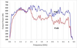
P1dB refers to the amp’s 1 dB compression point. This is the power level where, theoretically, a 10 dB increase in input power produces a 9 dB increase in output power. Effectively, the P1dB power is the top end of the amplifier’s linear region. Beyond the P1dB point, the amplifier will go further into compression. What this means to an EMC engineer, is that up to the P1dB point, the amplifier will operate within its linear region. This is important when testing to standards that have linearity requirements. For example, IEC 61000-4-3, the test method used for testing most commercial electronic products in today’s marketplace has a specific test as part of its calibration routine to verify that the amplifier used is operating in its linear region. If the amp is not, the test system fails calibration and cannot be used. If this is the test method you’re designing your system around, it would be wise to size your amplifiers according to their P1dB specification.
Psat is a common nomenclature for saturated power. Here, the amplifier is outside of its linear region, and an increase in input power will have no increase in output power. As we just discussed, Psat would not be the best choice for sizing an amplifier if you’re testing commercial products. However, many other test standards do not have such stringent linearity requirements. Standards like MIL-STD-461, DO-160, and ISO 11451/11452 for the military, aviation, and automotive industries respectively, fall into this category. In these cases, it would be acceptable to size an amplifier according to its Psat.
The last power definition we’ll touch on is rated power. The most important thing to remember about rated power is that there is no ‘textbook’ definition for rated power. It is a manufacturer-specific definition. One manufacturer may consider their rated power to be Psat, another may use P1dB, and another may use an entirely different definition. A 1,000 watt amplifier from Company A is not necessarily the same as a 1,000 watt amplifier from Company B. The point is, when looking at the rated power of an amplifier, it’s extremely important to understand the manufacturer’s definition of rated power.
Regardless of the definition of power you’re considering, it is always important to add margin onto what you think you need. In EMC testing, there are always unknowns. Poorly matched transducers, chamber loading/reflections, poor cables, and many more factors can result in the need for more power than expected.
Another important amplifier parameter to consider is amplifier harmonics. Harmonics are unwanted signals occurring at multiples of the fundamental frequency, and are an inherent type of distortion to all amplifiers. In EMC testing, it’s important to limit this type of distortion for two key reasons (among others). One being the repeatability of a test. RI and CI tests are swept in frequency and equipment under test (EUTs) are tested at a single frequency at a time, unless you are testing using multi-tone methodology. If an EUT fails and there is a great amount of harmonic distortion, it may not be clear whether the EUT failed as a result of the incident fundamental frequency or from one of its harmonics. A second reason is due to the prevalence of broadband measurement equipment. In most cases, EMC tests utilize broadband power meters to measure amplifier power and broadband field probes to measure the generated electric field. These types of devices are not frequency-selective and therefore cannot differentiate between a fundamental and harmonic signal. Additionally, if the EUT is a broadband device it may also fail as a result of the total spectrum power, including the fundamental and harmonics, rather than failing from any single signal.
Lastly, we’ll briefly discuss mismatch tolerance. Mismatch tolerance is the ability of an amplifier to handle unmatched loads, and thus varying amounts of reflected power. In EMC applications, especially at lower frequencies, transducers (antennas/clamps/etc.) can be a very poor match to 50 Ohms (typical nominal output impedance of RF amplifiers). Field reflections/standing waves can cause significant reflected power as well. During test, it is important to continue to deliver forward power as well as protect the amp from reflected power damage.
B. Antennas
Similar to amplifiers, antennas have many specification parameters, and certain parameters are more relevant in relation to EMC testing. When choosing equipment for radiated immunity, proper antenna selection is critical. Selecting the wrong antenna could mean limited exposure areas, insufficient fields, and other problems.
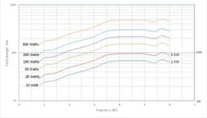
The first, and possibly most important, parameter to consider is the measured field strength of an antenna. This is empirical data of electric field strength produced by a given input power. This is highly useful for determining amp/antenna combinations for target immunity field strengths. Again, it’s very important to size the amp with margin (6 dB is good target, 3 dB minimum) as non-free space conditions can contribute considerable loss (not just cables!). Measured data can be scaled for other power inputs. Also, the measured field is typically lowest at the lowest operable frequency, corresponding to the lowest antenna gain. Keep in mind that test distance greatly affects field strength. Figures 2 and 3 show the measured field strength of a horn antenna at both 1 meter and 3 meter test distances. The difference caused by gain is apparent.
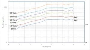
In general, the more power that is put into an antenna, the more field is generated. However, there is no antenna that can handle infinite power. Input power is often limited by the power handling of the RF connector on the antenna, but there are other factors that can limit the power further. Some antenna manufacturers will specify just a single power level for power handling. This, unfortunately, is ambiguous. Input power ratings really vary over frequency with power rating typically decreasing as frequency increases. Figure 4 shows the power handling of the same antenna represented in Figures 2 and 3.
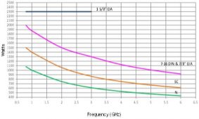
When a single value is presented, this can sometimes be misconstrued as the maximum power rating over the full band. If this isn’t made clear, it can be very easy to input this power level at a higher frequency and cause damage to the antenna. It should also be noted that these power levels are almost always defined as continuous or average power. Some immunity applications require high field strength pulsed tests. In these cases, large amounts of power are applied to the antenna but in very short durations and duty cycles. In these scenarios, the average power is very low, and therefore the antenna can handle much higher ‘peak’ power. Peak power handling of antenna is less well defined as voltage breakdown becomes the primary failure mechanism, and there are difficulties in characterizing this type of failure.
C. Measurement Equipment
The last equipment category we’ll touch on is measurement equipment. The most common types of measurement equipment used in immunity testing are RF power meters and electric field probes. Typically, both of these types of devices are broadband measurement devices, measuring RMS power or electric field of continuous wave (CW) signals. As we discussed before, this can present problems when harmonics or other unwanted signals are present, as these signals would contribute to the measured power or field. This is why it’s so important to limit harmonics and other unwanted signals. If frequency-selective measurements are desired, a receive antenna would need to be used along with a spectrum analyzer or EMI receiver. However, it should be noted that this method is typically not allowed in most test standards.
Another inherent problem of these devices is their ability, or rather inability, to accurately measure modulated signals. The majority of test standards require some type of modulation to be applied to the test signal. Traditional RF power meters and electric field probes are only capable of measuring CW signals, so either the test must first be calibrated without modulation applied, or the intented test signal must first be generated as a CW signal, then modulation applied. Either way, extra steps are involved. The adjective ‘traditional’ was used intentionally, as technologies are evolving, and some new RF power meters and electric field probes have the capability of measuring modulated signals. While these types of devices are gaining traction, the bulk of test standards are still written around the use of their traditional average measurement counterparts.
Summary
As you can see, there are many factors to consider when selecting equipment for EMC testing. It’s important to fully understand the multitude of requirements and specifications of not only the equipment itself, but the standards documents that dictate the tests. Of these equipment parameters, many are typically presented for a given piece of equipment, but not all parameters may be relevant to your particular application. With an in-depth knowledge of these parameters, it can be much easier to select the proper equipment for EMC testing applications.
