INTRODUCTION
There are two principal types of emission measurements in the world of electromagnetic compatibility, conducted emission and radiated emission. The conducted emission measurements are either a voltage-capacitive tap type of measurement (typically on a power line) or they are a current-clamp type of measurement (typically on a signal line).
Radiated emission measurements are unique in that they must always state “the horizontal distance from the Equipment-Under-Test (EUT) to the receiving antenna” in order to compare the measured values to the appropriate regulatory limit. This horizontal distance, which is typically one, three, five, ten, or 30 meters, and the limits (both regulatory and standard-based) associated with those horizontal distances are the subject of this article.
ONE-METER MEASUREMENTS
There are two well-known EMC-measurement standards that reference a one-meter measurement distance from the EUT to the receiving antenna for radiated emissions. They are MIL-STD 461 and RTCA DO-160. There are other EMC standards that also use the one-meter horizontal-distance; one primary example is CISPR 25 – Electromagnetic Disturbances Related to Electric/Electronic Equipment on vehicles and Internal Combustion Engine Powered Devices.
First released in 1968, MIL-STD 461 has always specified a one-meter EUT-to-antenna distance; originally inside of a shielded room with bare walls and, then, in later revisions, inside of a shielded room with anechoic material on the walls. MIL-STD 461 (the latest version is MIL-STD-461G – December, 2015) is the standard used to test and qualify products sold to United States Military organizations and it has been widely duplicated in other countries’ specifications for EMC of military electronic products.
RTCA DO-160 was first published in 1975 and is the EMC standard for commercial aircraft electronics in the United States and it is maintained by RTCA (an organization incorporated in Washington, DC). The latest version is RTCA-DO-160G, which was released in December of 2010. It’s Section 21 addresses “Emission of Radio Frequency (RF) Energy” and it specifies a one-meter antenna distance inside of a shielded room with anechoic material (electromagnetic field absorbers) on the ceiling and about one-half of the wall surfaces. The European version of RTCA-DO-160 is EUROCAE ED-14 (EUROCAE is the European Organization for Civil Aviation Equipment; RTCA and EUROCAE work closely together and their standards are harmonized). CISPR 25 specifies a one-meter antenna distance to be used for radiated emissions from Components/Modules in an Absorber Lined Shielded Enclosure (ALSE).
The one-meter antenna distance has worked well for both Military Standard approved products and for Commercial Aviation approved products. A one-meter separation distance is a reasonable distance between an RF source and receptor of RF energy inside of a plane, a tank, or a ship. With the exception of CISPR 25 (where, again, a one-meter antenna distance is logical for closely located electronics in a vehicle), major measurement standards for terrestrial-based commercial products have conspicuously avoided a one-meter antenna measurement distance.
THREE-METER MEASUREMENTS
Three-meter measurements are growing increasingly prevalent in the measurement world. They have been used by the United States Federal Communications Commission (FCC) for a number of years. Specifically, measurements of Class B digital devices (computers and similar devices) have been permitted at 3-meters since 1979 (FCC Docket 20780). The rationale for a three-meter measurement distance for Class B equipment was that small business computers (as a source of RF energy) would be closer to the potential receptor of energy (TV, radios, etc.) than a large Class A Computer. The simulated model of the source-receptor duality for Class B Computers was a business having a small computer and an apartment (3-meters away) having the TV or radio receiver.
Par. 15.109 (Radiated emission limits) of the FCC Rules says:
(a) Except for Class A digital devices, the field strength of radiated emissions from unintentional radiators at a distance of 3 meters shall not exceed the following values:
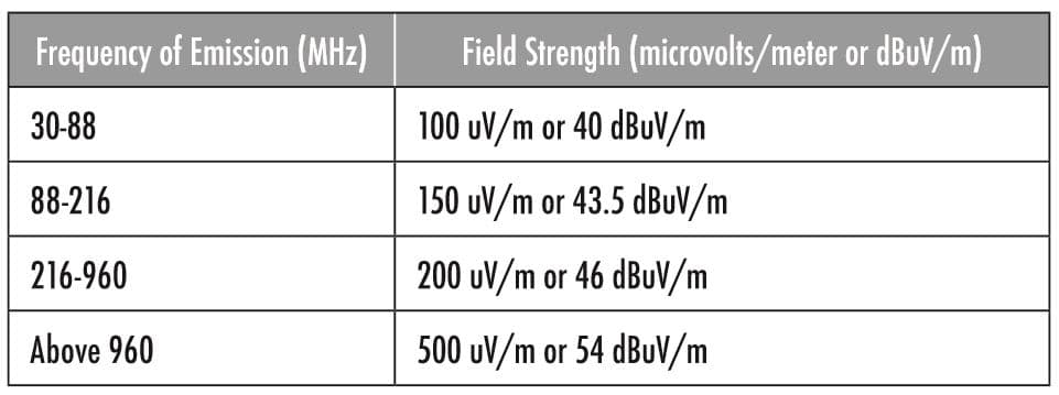
Three-meter measurements from 30-1000 MHz can be made in an Open Area Test Site or, more likely these days, in a three-meter semi-anechoic chamber due to the increasingly higher-ambient electromagnetic levels found in the environment. Fully anechoic rooms are also becoming more prevalent for 3-meter measurements.
It should be noted that three-meter measurements are also specified for radiated emission measurements for both Class A and Class B products above 1 GHz for both FCC Rules and International Standards for electromagnetic emissions.
Also, CISPR 32 – Edition 2.0 was published in 2015 and it allows Class A and Class B computers to be tested at a 3-meter horizontal distance from 30-1000 MHz.
FIVE-METER MEASUREMENTS
Radiated emission measurements made at a 5-meter horizontal antenna distance are being made in the commercial world. This is a “compromise” distance between 3-meters and 10-meters. The advantages to measurements made at 5-meters are that you can have a larger turntable in a 5-meter chamber and it is “easier” to meet the Volumetric Normalized Site Attenuation criteria for 3-meter distances in a larger 5-meter room.
However, at the present time, no standards specifically call out a 5-meter “standard” measurement distance. Limits specified at 3-meters or 10-meters are interpolated to a 5-meter distance using the inverse-distance fall-off guidance for a number of standards.
TEN-METER MEASUREMENTS
Many EMC technical experts consider the ten-meter measurement distance to be the “Gold Standard” in today’s electromagnetic emission measurement world for Class A equipment. Ten-meter measurements are made at both Open Area Test Sites and in SemiAnechoic Chambers. The semi-anechoic chambers are increasingly popular due to the steadily rising ambient levels in the real world because of digital TV and other new electronic developments.
Other advantages of the 10-meter antenna distance is that it allows a larger turntable to be used, and, therefore larger products can be tested with the receiving antenna in the “far-field” of the product’s emanations. For example, at 10-meters, the EUT is one wavelength away from the antenna at 30 MHz, two wavelengths away at 60 MHz and three wavelengths away at 90 MHz. In contrast, equipment tested at 3-meters is not one wavelength away from the antenna until frequencies are at 100 MHz, two wavelengths away at 200 MHz, and three wavelengths away at 300 MHz.
Again, the FCC Rules are strongly stated in Par. 15.109 (Radiated emission limits) where it says:
(b) The field strength of radiated emissions from a Class A digital device, as determined at 10 meters, shall not exceed the following:
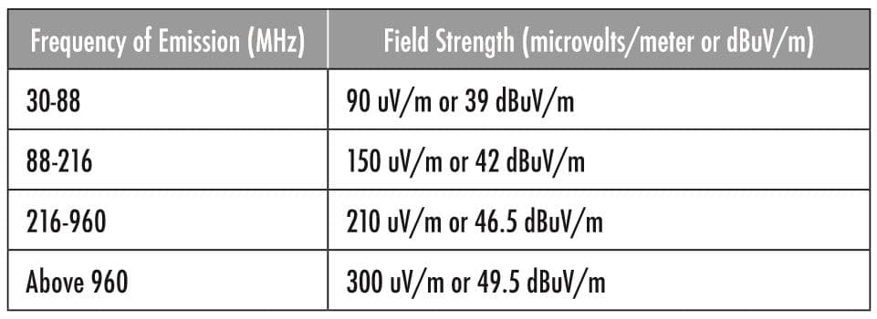
NOTE – Several Asian countries require strict acceptance of 10-meter radiated emission measurements for Class A equipment when specified in their regulatory requirements based on international standards.
30-METER MEASUREMENTS
Thirty-meter measurements were the preferred measurement distance for Class A Digital Devices when the FCC rules were first released for ‘computers’ back in 1979.
The main reason for this was the CBEMA Report[1] released in 1977 in response to FCC Docket 20780[2]. The 1977 CBEMA report states “89 percent of receiving antennas found within 100 meters of commercial Electronic Data Processing/Office Equipment installations can be expected to be 30 meters or more from the installations.” Therefore, the CBEMA report chose “30 meters” as a reasonable control distance for radiated emission limits from Class A computers.
Also, the FCC imposed rules at 30 meters (approximately 100 feet). In a historical article[3] by Herman Garlan, Chief of the Radio Frequency (RF) Devices Branch in 1973, he states, “The rules then in effect (for operation with a duty cycle) permitted a field-strength level of 50 uV/m at 100 feet (30 meters) on frequencies between 88-108 MHz.”
Also, in the 1970s, the German VDE testing authorities used a 30-meter test distance for much of their testing[4].
Problems with relatively high-ambient levels from 30 MHz to 1000 MHz at 30 meters made it very difficult to make measurements. In addition, the antenna mast had to be 6 meters high at 30 meters, which was a challenge for EMC test labs. Normalized Site Attenuation (NSA) was also a technical challenge for 30-meter test sites; it was achievable but time-consuming and more complex than NSA at 10 meters or 3 meters.
Because of the above difficulties, in the early 1980s the FCC released Docket 80-284, which eventually changed the preferred test distance for Class A digital devices to 10 meters. So, in the United States, the 10-meter distance for Class A devices has been the dominant distance for the last 35 years.
NOTE – There are strong technical arguments for using a 30-meter test distance for frequencies BELOW 30 MHz due to the longer wavelengths of the electromagnetic energy at lower frequencies.
INTERNATIONAL STANDARDS
Despite a number of changes to FCC Rules since the first publication of this article in 2010, Part 15 of the FCC rules still states in 15.109 (g):
“As an alternative to the radiated emission limits shown in paragraphs (a) and (b) of this section, digital devices may be shown to comply with the standards contained in the Third Edition of the International Special Committee on Radio Interference (CISPR), Pub. 22, “Information Technology Equipment (ITE) – Radio Disturbance Characteristics – Limits and Methods of Measurement.”
The Third Edition of CISPR 22 (1997) has the following limits:

NOTE – The CISPR 32 – 2015 limits for Class A and Class B are same as CISPR 22 – 1997 at 10 meters.

If we compare the FCC and CISPR 22 (1997)/CISPR 32 (2015) limits at 10 meters for Class A equipment, we have the following table:
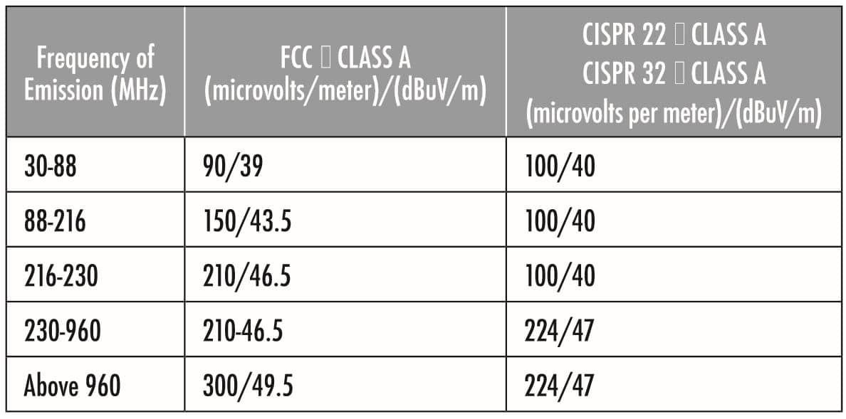
If we compare the FCC and CISPR 32 (2015) limits at 3 meters for Class B equipment, we have the following table:
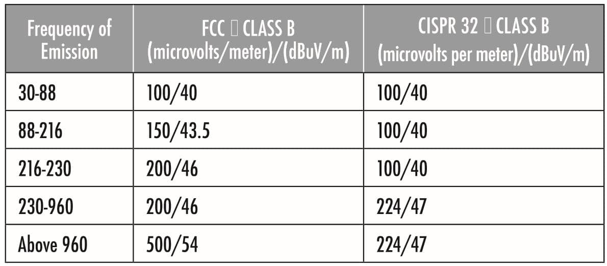
The two sets of limits (FCC and CISPR 22/CISPR 32) are reasonably close for Class A equipment at 10 meters and further apart for Class B equipment at 3-meters.
INVERSE DISTANCE FALL-OFF
The inverse distance fall-off theory, also called the 1/r (1/d) theory, assumes a small source in a free-space (free-field) environment. In general, these two conditions (small source and free-space) are not met in a typical EMC measurement.
Most products have lengths and widths so they are not necessarily a “small source”, for example, a table-top product is placed on a non-conductive table 0.8 meter above the ground plane and the power cord from EUT starts at the ground plane and reaches up to the EUT. The non-conductive table has a nominal size of 1.0 meter wide and 1.5 meters long. The product under test is usually smaller than the table but it is possible for it to be bigger than the standard table.
The ground plane is typically a solid metal floor or a metallic screen with small openings. In both cases, a reflected wave from the ground plane complicates the measurement of the radiated fields from the EUT. There have been a number of technical studies on the fall-off of electromagnetic fields from measurements close to a product versus a regulatory limit at a further distance from the product. We will look at a number of those studies in this paper.
TECHNICAL STUDIES JUSTIFYING INVERSE DISTANCE FALL FOR REAL PRODUCTS
Note: The author was unable to find any technical paper that justifies an inverse-distance fall-off for real products in an Open Area Test Site or a Semi-Anechoic Chamber especially for distances below 10 meters and frequencies between 30 and 1000 MHz.
TECHNICAL STUDIES QUESTIONING INVERSE DISTANCE FALL FOR REAL PRODUCTS
One of the first papers on “Falloffs” was written by William E. Cory and Frank C. Milstead in 1969[6]. It stated: ”Propagation predictions in the near field, while less accurate, can be made to within about 10 db.”
Albert A. Smith, Jr. wrote a paper in 1969[7], which modeled surface waves and space waves and found a complex relationship below 100 MHz. However, the paper goes on to say “Above approximately 100 MHz the space wave predominates for ‘source and receiving heights of 1 meter’ and the induction fields are negligible for ‘antenna to EUT distances’ greater than one meter.”
Herman Garlan’s paper[8] says in the “History of Part 15” section “The original low-power rule, the λ/2π rule, was adopted in 1938. This rule provided a reasonable operating standard on frequencies up through the AM broadcast band – up to 1600 kHz. This standard was still usable up to about 10 MHz where the λ/2π rule permits a field of 15 uV/m at about 5 meters or 16 feet. While this standard served the needs of 1938, by the end of World War II, in 1945, it was hopelessly inadequate.”
The CBEMA paper was published in 1977; it was a comprehensive review of the interference potential of large computers. It says, “A practical site that allows measurements at the minimum test distance of 3 meters is shown in Figure 10-3. Results of measurements in such practical test sites at varying distances between the equipment being tested and the measurement antenna, have been found to be within +/- 6 dB of those predicted using a 20 dB/decade fall-off relationship between the equipment and the antenna.”
Yet another paper was published in 1980 by Robert F. German and Ralph Calcavecchio[8]. This paper says “It is generally accepted that EMI radiated from large equipment should be measured at a distance of 30 meters. Measurements in the 30-1000 MHz frequency range at this distance usually are in the far-field of the source. However, ‘due to ambient conditions’ it is desirable to allow measurements to be made at distances of 3, 10, or 30 meters. It will be seen that, when appropriate assumptions are made, a measurement technique can be identified that relates measurements made at different distances by the 1/r attenuation factor of free space propagation.” The paper goes on to say “An EMI source is simulated by an electrically short dipole antenna. Actual EMI sources may be more complex and the topic of future work.” Thus, the paper concludes 1/r works for “electrically short dipoles.”
Another paper from two engineers who worked at IBM[9], concluded “The radiation from more than 25 different products showed a great variation from the 20 dB attenuation often assumed between three and 30 meter field strength levels.” It stated further “These products varied in maximum linear dimension from one to 10 meters.” Also, the paper had three Efield falloff figures; “In all three falloff figures, it is noted that the radiated field at few frequencies attenuate at a rate of 20 dB per decade distance). This does not contradict the theoretical 20 dB falloff in free space between two points in the far-field located at a distance ratio of 10 to 1 away from a point source or from a dipole antenna small relative to the wavelength radiated. In fact, a very large source (see Figure 8b) could in the extreme show a falloff approaching 0-dB because it contains a large number of geometrically distributed sources, both horizontally and vertically. The fields from such multiple sources superimpose and may generate an almost plane wavefront (a plane wavefront exhibiting 0-dB falloff).”
Another paper[10], by Arlon T. Adams, Yehuda Leviatan, and Knut S. Nordby, covered a study concerned with the near fields of computer products. The study states that “The measurement distances of 3 to 30 meters may lie in the near or the far field, depending on the dimensions of the product and the frequencies emitted.” Furthermore, the study says, “In other words, the average slope in the oscillatory region is less than 20 dB per decade (it is about 10 dB per decade.) In other words, a product just meeting FCC rules at 3-m distance may exceed the rule when measured at 30 m. Thus, measurements made at short distances and then normalized to larger distances will yield far-fields smaller that they should be.” An additional paper by Adams and Nordby[11] reemphasized the above points.
In 1987, there was an article published in the 1987 IEEE International Symposium on EMC record[12] by J. D. Gavenda concerning vertical dipole sources in EUTs. His paper stressed the point that vertical electrical fields are also produced off the end of a horizontal electric dipole, and broadside to a horizontal magnetic dipole. The paper states “In free space at distances large compared with the wave-length and with the maximum dimensions of the EUT, the field strength falls off inversely with distance. However, the presence of a conducting ground plane causes reflected signals, which interfere constructively or destructively, depending on height above the ground plane and frequency, with the direct signal. This invalidates any simple inverse-distance falloff rule, so correction factors must be used in the extrapolations.” In the paper, he has a falloff figure for a vertical dipole FROM 3 TO 10 meters that is a shallow-v-shaped with a only a 7 dB falloff from 30 to 100 MHz, a mere 4 dB falloff from 100 to 300 MHz, and, then, back to about a 7 dB falloff from 300 – 1000 MHz.
A very well known and respected paper was written in 1987 by Joseph DeMarinis of Digital Equipment Corporation[13]. One of the goals of this paper was the “Prediction and Measurement of correlation errors between 3-meter and 10-meter site distances and development of bands of confidence around such correlation.” In its Introduction, the paper says “It is well known that signal falloff versus site distance does not follow the 1/distance rule which is proscribed by the regulatory standards and that very large correlation errors can exist between test results taken at different distances. It was of particular interest to the project at hand, to try to understand the relationship between 3-meter and 10-meter sites.” The resulting data of the study showed a falloff of only 4 to 9 db from 30-200 MHz for vertical signals and a falloff between 9 and 14 dB for horizontal signals. From 200- 1000 MHz, the falloff for vertical signals ranged from 3 to 11 db and for horizontal signals it ranged from 8 to 13 db. All of this data, predicted and actual, was for Open Area Test Sites.
In 1993, three engineers from Austria wrote a paper on radiated emission testing at 3 meters[14]. This paper investigated a difference in extrapolation factors (0 db/decade in CISPR 11 and 20 dB/decade in CISPR 22) that existed at that time. Measurements were made at an Open Area Test Site and showed a range of falloff from 1 to 18 dB from a setup representing a typical personal computer. The paper presented worst-case extrapolation factors, for 3 and 10-meter test results, for both horizontal and vertical polarizations.
Another paper in 1996 by Christopher l. Holloway and Edward F. Kuester[15] looked at the comparison of OATS and semi-anechoic chambers. It stated that by looking at site attenuations of the two venues an equivalent comparison could be made. It concluded that “This comparison is generally quite good at frequencies higher than 300 MHz, but at lower frequencies (30 -300 MHz), large discrepancies are often observed due to reflections from the chamber walls.”
Finally, a paper given in 2009 by Blankenship, Arnett, and Chen described another perspective on looking at the falloffs from 3 to 10 meters[16]. This paper also predicted a complicated falloff curve for signals between 3 and 10 meters and it was based on testing in semi-anechoic chambers.
CONCLUSIONS AND RECOMMENDATIONS
It can be seen that over the past forty years that the measurement of radiated emissions from electronic equipment has been an active topic.
The military and commercial avionics, as well as automotive, products have consistently used (and continue to use) a one-meter antenna distance for radiated emission. However, they have made improvements in the shielded-room locale by adding anechoic material to the ceiling and, at least, part of the wall surfaces in the chamber thus reducing reflections and increasing the accuracy of the test results over the past five decades.
It is also observed that there has been a trend over the last forty years towards making measurements on commercial products at antenna distances closer and closer to the Equipment Under Test. We have gone from an environment of making measurements at 30 meters on Class A commercial electronic products to an environment of making measurements at 3 and 10 meters.
The risk with moving closer to the product under test is that the receiving antenna can be immersed in the near-field environment of the EUT. When this happens, and it does at various distances and frequencies depending on the size and internal sources in the product, predicting falloffs of electromagnetic energy with the inverse distance falloff formula (1/r distance factor) does not work and the fields measured at distances further from the product will, in general, be at a higher amplitude than that predicted with a 1/r falloff.
CLASS B PRODUCTS TESTED AT 3-METERS
Since Class B products are already commonly tested at 3 meters for FCC regulations from 30 MHz to 1000 MHz and Class A and B products are tested at frequencies above 1000 MHz at 3-meters both in the USA and worldwide, it is obvious that 3-meter measurements are widely accepted around the world. If Class B products are tested at 3 meters as per CISPR 32, there would be no need for discussions relative to falloffs from 3 to 10 meters and the USA and International limits are very close which may lead to the desired goal of “harmonization.”
CLASS B PRODUCTS TESTED AT 5-METERS
Class B products tested at 5 meters need to be investigated further as to their falloffs since there has been a limited amount of research done on the falloffs of fields from 3 to 5 meters and 5 to 10 meters over the frequency range 30 -1000 MHz.
CLASS A PRODUCTS TESTED AT 10-METERS
One alternative to the Class A issue is to mandate all Class A products be tested at 10 meters with no exceptions. Then, there would be no falloff debates since Class A products could not be tested at a closer distance.
However, if industry would like to test Class A products at 3-meters, as per the latest version of CISPR 32, there should be a correction factor applied to handle that situation. It is probably not 0 db (as was used in CISPR 11 in 1998) and it is probably not 10 dB (as used in CISPR 32 in 2015). It is some factor between those two theories and it should be frequency dependent.
A proposal along those lines would be a correction factor (not equal to the widely accepted 10 dB) that would be added to the 10-meter regulatory limit when the product is tested at three meters. As a first estimate, the following correction factors (instead of a de facto +10 dB) are proposed:
30 – 100 MHz – + 6 db
100 -300 MHz – + 3 dB
300 – 600 MHz – + 6 db
600 – 900 MHz – + 7 dB
900 – 1000 MHz – + 8 db
So, for example, at 120 MHz, the limit would be 40 plus 3 or 43 dBuV/m (instead of 40 plus 10 or 50 dBuV/m) when a Class A EUT is measured at a 3-meter antenna distance. (See Table A.2 of CISPR 32).
These proposed correction numbers are consistent with references[12] and[16]. This set of correction factors would cover the vertical field falloffs and would be even more conservative for the horizontal field falloffs (which are closer to the 1/r falloff curve).
REFERENCES
[1] CBEMA Report – CBEMA/ESC5/77/29 – “Limits and Methods of Measurement of Electromagnetic Emanations from Electronic Data Processing and Office Equipment,” 20 May 1977.
[2] Federal Communications Commission – Notice of Proposed Rule-Making – FCC Docket No. 20780 – “In the Matter of Amendment of Part 15 to redefine and clarify the rules governing restricted radiation and low-power communication devices,” – Adopted April 14, 1976 and published on April 23, 1976 at 41 Federal Register 17938.
[3] Herman Garlan, “FCC Improves Spectrum Utilization Thru Use of Part 15,” 1973 IEEE International Symposium on Electromagnetic Compatibility, IEEE 73 CHO 751-8 EMC, June 20-22, 1973.
[4] Herbert K. Mertel, “VDE Interference Regulations of West Germany,” ITEM 1980, R & B Enterprises, Plymouth Meeting, PA 19462, 1980.
[5] Federal Communications Commission – Notice of Proposed Rule-Making – FCC Docket No. 80-284, “Test Methods for Part 15 Devices, June, 1980.
[6] William E. Cory and Frank C. Milstead, “The Effects of the Local Environment on Interference Measurement and Prediction,” 1969 IEEE Electromagnetic Compatibility Symposium Record, IEEE 69C3-EMC, June 17-19, 1969.
[7] Albert A. Smith, Jr., “Electric Field Propagation in the Proximal Region,” IEEE Transactions on Electromagnetic Compatibility, Vol. EMC-11, No. 4, Nov. 1969.
[8] Robert F. German and Ralph Calcavecchio, “On Radiated EMI Measurement in the VHF/UHF Frequency Range,” 1980 IEEE International Symposium on Electromagnetic Compatibility, IEEE 80CH1538-8EMC, 1980.
[9] T. M. Madzy and K. S. Nordby, “IBM Endicott EMI Range,” 1981 IEEE International Symposium on Electromagnetic Compatibility, IEEE 81CH1675-8, August 18-20, 1981.
[10] Arlon T. Adams, Yehuda Leviatan, and Knut S. Nordby, “Electromagnetic Near Fields as a Function of Electrical Size,” IEEE Transactions on Electromagnetic Compatibility, Vol. EMC-25, No. 4, November 1983.
[11] Arlon T. Adams and Knut S. Nordby, “Electromagnetic Near Fields as a Function of Electrical Size,” 1983 IEEE International Symposium on Electromagnetic Compatibility, IEEE 83CH1838-2, August 23-25, 1983.
[12] J. D. Gavenda, “Effect of Electromagnetic Source Type and Orientation on Signal Falloff with Distance,” 1987 IEEE International Symposium on Electromagnetic Compatibility, IEEE 87CH2487-7, August 25-27, 1987.
[13] Joseph DeMarinis, “Studies Relating to the Design of Open Field EMI Test Sites,” 1987 IEEE International Symposium on Electromagnetic Compatibility, IEEE 87CH2487-7, August 25-27, 1987.
[14] H. F. Garn, E. Zink, and R. Kremser; “Problems with Radiated-Emission Testing at 3 m Distance According to CISPR 11 and CISPR 22,” 1993 IEEE International Symposium on Electromagnetic Compatibility,IEEE93CH3310-0, August, 1993.
[15] Christopher l. Holloway and Edward F. Kuester, “Modeling Semi-Anechoic Electromagnetic Measurement Chambers,” IEEE Transactions on Electromagnetic Compatibility, Vol. 38, No. 1, February, 1996.
[16] Ed Blankenship, David Arnett, and Sidney Chan; “Searching for the Elusive Correction Factor between 3m and 10m Radiated Emission Tests,” 2009 IEEE International Symposium on Electromagnetic Compatibility, IEEE CFP09EMC-CDR, August 17-21, 2009.
