Well we are still waiting to see if borrowing 3D EM software is on the cards. I should know soon, one way or the other. I hope it happens, but for now let’s keep holding off on Elephant #3, ‘Fixing the Broken Automotive Test Fixture,’ In the meantime, we can continue the engineering approach on determining a practical level of harmonics in RF immunity for Elephant #2, ‘Disharmony in Harmonic Limits,’ which became a subset of our project on linearizing EMC amplifiers.
Also, I listened in on the Agilent July 24 webcast, “a day in the life of your cell phone,” which was pretty good. During the webcast, I asked via the dialog box what the maximum radiated power from a cell phone was, and when did it emit this maximum level (at switch-on, when setting up an incoming call, etc)? The answer given was “when the cell phone is furthest away from a base station.” This is a partial answer and I suspect only applies to when the transmission channel between the base station and the cell phone is already set up. It’s not the answer we wanted, so I will ask for further clarification from the webcast organizers. Until they get back to me, we will hold off on ‘The Cell Phone Threat.’
The Linearization of EMC Amplifiers
Reminder: In previous posts on this thread, we asked the $64,000 question,”what is a practical level of harmonics in a RF immunity system?”
To help answer this question, we derived the equation for the amount of harmonic field compared to the wanted test frequency field. We christened this test field integrity indicator as E2dBc.
We then used the equation to determine what level of amplifier harmonics would create the commercial limit of -6dBc test field harmonics. This came out at -10dBc, to which we added a safety factor of 3dB, giving our initial determination of sensible amplifier harmonics as -13dBc.
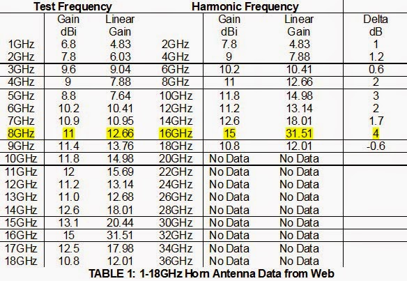
The EMC amplifier linearization exercise we are conducting is over 1-18 GHz, so previously we chose a horn antenna with characteristics very similar to the majority of 1-18 GHz horn antennas out there in the marketplace. Their performances are so close I think we can assume the various suppliers use the self-same design or rebrand the self-same antenna. For ease of reference, the amplifier data table is repeated here.
For the particular antenna in question, the relevant worst-case gain difference was at 8 GHz when the 8 GHz linear gain G1 was 12.66 and the 16 GHz linear gain G2 was 31.56. The table already states the relative difference for us in decibels as 4dB. We will need this later.
Separately, we established the amount of harmonic field permitted in commercial product testing as up to one-third of the total test field.
One-third seems on the high side, so let’s play with the E2dBc equation a little longer to try and justify a level suited to both commercial and automotive RF immunity testing.
We want to flit easily between the variables so we will make life easy for ourselves by deriving E2dBc in its simplest and most useful form.
E2dBc = 10log10 [G2.P2]
[G1.P1]
Expanding gives:
E2dBc = 10log10 [G2/G1] + 10log10 [P2/P1]
Which, purely for convenience, we will rearrange to read:
E2dBc = 10log10 [P2/P1] + 10log10 [G2/G1]
But 10log10 [P2/P1] is P2dBc and 10log10 [G2/G1] is G2dBc.
That is P2dBc is the level of the harmonic relative to the fundamental frequency in dBs (worst-case is always stated on the amplifier data sheet) and G2dBc is the gain the antenna presents to the harmonic relative to the gain the antenna presents to the fundamental, again in dBs (obtainable by inspection of the antenna data sheet).
Therefore, the test field integrity indication equation is:
E2dBc = P2dBc + G2dBc
Now it is simplicity itself to flit between a) E2dBc, the harmonic level compared to the fundamental in the test field itself, and b) P2dBc, the harmonic level compared to the fundamental from the amplifier, and c) G2dBc, the gain the antenna presents to the harmonic compared to the gain it presents to the fundamental in dBs.
Now we use the new equation to establish the field harmonic level E2dBc if we use the proposed -13dBc amplifier harmonics.
E2dBc = P2dBc + G2dBc
E2dBc = -13 + G2dBc
We already know from the antenna table that the worst-case G2dBc is 4dB.
E2dBc = -13 + 4
E2dBc = -9
Impact of First Determination of Amplifier Harmonics on the Integrity of the Test Field
If E2dBc is changed from -6 to -9, what change does this cause in the make-up of the commercial test field?
The Total Test Field E = E1 + E2
If E2dBc = -9, that means 20 log10 [E2/E1] = -9
E2/E1 = antilog10 (-9/20)
E2/E1 = 0.355
E2 = 0.355*E1
Substituting this into Total Test Field E = E1 + E2
E = E1 + 0.355*E1
E = E1 (1 + 0.355)
E = 1.355*E1
E1 = E/1.355
E1 = 0.74*E
This means E1 is pretty close to 75% of the total field which in turn means E2 is close to 25% of the total field.
For the calibrated commercial test field of 18v/m, 13.5v/m will be at the intended frequency and 4.5v/m will be at the harmonic frequency.
For the automotive test field of 200v/m, 150v/m will be at the intended frequency and 50v/m will be at the harmonic frequency.
It is plain that this basic method could be used to see the effect of amplifier harmonic limits anywhere between -10dBc and -20dBc.
In terms of our TWT Amplifier linearization target, I believe we are there at -13dBc.
Next time we will look at the diminished return between improved amplifier harmonics and the integrity of the total test field.
-Tom Mullineaux


