Jan SROKA
Abstract.
There is still big improvement potential in reproducibility by EMC testing. CISPR groups permanently work on it. The document CISPR 11 + A1 in act is issued in 2010. It is already in general maintenance revision which will supersede the existing one in 2015. New regulations included in this document such as: mandatory application of the Common Mode Absorbing Devices, precise definitions of the EUT volume and the small EUT surely will improve reproducibility of the radiated emission. The same concerns the treatment of the special earthing terminal by conducted emission if ambiguity, which is evidently an oversight, will be eliminated
Introduction
The document CISPR 11 + A1 in act is issued in 2010. It is already in general maintenance revision which will supersede the existing one in 2015. Many regulations which improve reproducibility of the measurements are included in it. Among others there are:
-mandatory usage of the Common Mode Absorbing Devices by radiated emission measurements up to 1GHz,
-precise definition of the EUT volume,
-bonding of the earthing terminal.
The reader should get familiar with these requirements in order to adopt them just on time.
After years of discussions on the CISPR meetings, the experts agreed that common mode impedances of the lines connected to the EUT have significant influence on the radiated emission below 1GHz. Specially it concerns the small table top equipments . Therefore it is required to mount the Common Mode Absorbing Device CMAD on all lines i.e.: power input and output as well communication and signal lines. CMADs should stabilize the common mode impedance, independently on the termination impedance of the line.
In the document [2] technical specification of the CMAD are established. Document [3] is the first one according to which the usage of the CMAD is mandatory.
The CMAD can, but may not decide about the EUT volume. Definition of the EUT volume changes also definition of the antenna – EUT distance.
The term small EUT gives the decision criterion about ability of testing in the 3m distance. It is firstly introduced in the document [1]. However only precise definition of the EUT volume in document [4] eliminates interpretation ambiguity of this term.
In many cases the EUTs have additional earthing terminals, despite the PE strain in the mains cable. It concerns mainly the EUTs with big dimensions and big rated power, intended for industrial applications. In the existing documents there were no regulations on how to treat them. In consequence there test hoses interpreted this in different ways. The document [4] terminates this arbitrator by radiated emission but there is still ambiguity by conducted emission.
Common Mode Absorbing Device CMAD
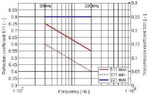
According to the document [2] reflection coefficient S11 of the CMAD must be within the following limit range (red lines in Fig. 1):
-upper limit 0,75 at 30MHz and 0,55 at 200MHz, decreasing linearly with the logarithm of the frequency (continuous line in Fig. 1),
-lower limit 0,6 at 30MHz and 0,4 at 200MHz, decreasing linearly with the logarithm of the frequency (dotted line in Fig. 1).
Transmission coefficient S21 must be less then 0,25 in in the frequency range from 30MHz to 200MHz (blue line in Fig.1). These coefficients are referenced to the characteristic impedance ZC of the cylindrical wire with d diameter, placed in the height h over the metal reference. It can be expressed as follows

in which: Z0 – wave impedance of the vacuum.
Typical value of d is 4cm. The height h depends on the clamp construction. Characteristic impedances ZC for typical clamps are gathered in Table 1.


Asymmetric impedance of the line placed in the CMAD is as follows [5]

by which: ΓL – reflection coefficient, on the clamp port opposite to the EUT port. It is consequence of mismatching with ZC.
For negligible small coefficients S12 and S21 it is simplified to
![]()
Analysis of Eq. (2) and (3) leads to the conclusion that both requirements imposed on the CMAD are necessary. Coefficient S11 ensures required impedance Z1 on the EUT port. Small coefficients S21 = S21 makes this impedance insensitive on the termination impedance of the line on the side opposite to the EUT.
Neither Secondary Absorbing Devices SADs, used by the measurement of the emission of power according to CISPR 16-1-3, nor decoupling clamps recommended by the standard EN 61000-4-6 do not fulfil the requirements of the CMAD. For testing houses it means the new purchase.
Set-up for the measurement of the radiated emission up to 1GHz
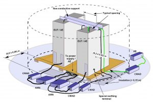
![Fig.2. Set-up for the table top equipment acc. to [4].](https://interferencetechnology.com/wp-content/uploads/2014/12/Untitled-21-300x159.jpg)

![Fig.4. Measurement set-up along with the antenna acc. to [4].](https://interferencetechnology.com/wp-content/uploads/2014/12/Untitled-23-300x169.jpg)
-the term: 3m, or 10m measurement set-up is no more sufficient characterisation of the ability of the chamber. It must be accompanied with the information about the maximal volume of the EUT which can be measured. For this volume the Normalised Side Attenuation NSA [6] must be verified. Usually this volume is equal or less than the diameter of the turn floor.
-The place of the antenna in the chamber is not fixed any more. It changes depending on the diameter of the EUT volume.
EUT earthing
In document [4] for the first time special earthing terminal (chapter 8.1, 8.2, Fig. 3) is introduced. If the EUT is fitted with special earthing terminal, despite the PE strain in the mains cord, then this must be connected to the ground reference during radiated and conducted emission measurements with an as short as possible uninductive lead. However in the same document in chapter 7.5.3.2 in which the set-up for the conducted emission measurement is defined, two other earthing terminals are defined, namely:
-earth connections for safety purposes,
-other earth connections (e.g. for EMC purposes).
These earth connections should be connected to the reference earth point of the Artificial Mains Network AMN.
Conclusions
The document [4] in preparation introduces several new requirements which precisely describes the test set-ups by radiated and conducted emission measurements. It surely improves reproducibility of the measurements.
The document [1] gives the criterion according to which the EUTs can be measured in the 3m set-up (small EUT). However only precise definition of the EUT volume in document [4] gives no doubts in interpretation of the small EUT. This definitively terminates misusing of the 3m chambers for the measurement of not small EUTs.
Moreover the term of the EUT volume enables the differentiation of the 10m chambers due to the volume with verified NSA.
The document [4] shows two excluding ways of the treatment of the earth terminals by conducted mission measurements. It is evidently oversight which can have significant influence on the measurement results. Hopefully the national CISPR Committees will see it and will cause correction of this ambiguity.
BIBLIOGRAPHY
[1] CISPR 11 + A1: Industrial, scientific and medical equipment – Radio frequency disturbance characteristics – Limits and methods of measurement: 2010.
[2] CISPR 16-1-4: Specification for radio disturbance and immunity measuring apparatus and methods – Part 1-4: Radio disturbance and immunity measuring apparatus – Antennas and test sites for radiated disturbance measurements. 2010.
[3] CISPR 16-2-3: Specification for radio disturbance and immunity measuring apparatus and methods – Part 2-3: Methods of measurement of disturbances and immunity – Radiated disturbance measurements. 2010.
[4] CISPR/B/598/CDV: Industrial, scientific and medical equipment – Radio frequency disturbance characteristics – Limits and methods of measurement: 2014.
[5] Jan Sroka: Niepewność pomiarowa w badaniach EMC, pomiary emisyjności radioelektrycznej OWPW, Warszawa, 2009.
[6] Jan Sroka: |ΔNSASAC|>4dB. – co dalej? Przegląd Elektrotechniczny R. 90 NR 7/2014, ss. 14 -17, 2014.


