Introduction
For Army, Navy, and Air Force military equipment and DO-160 commercial aircraft avionics, radiated susceptibility test levels as high as 200 V/m may be specified. As always, it is better to design immunity to the test levels into equipment than to wait until equipment is completed and then perform tests.
This article assumes the worst-case qualification test levels of 200 V/m. If the radiated susceptibility test levels are lower than all of the predicted circuit test levels can be reduced accordingly.
This article shows levels induced into the circuits when 200 V/m is incident on the equipment’s shielded or unshielded cables. With this information, circuits can be designed to be immune to the levels. The high-level tests require high-power amplifiers and antennas capable of coping with the power. Although common in test labs, these are not so common in manufacturers’ test facilities. The circuit-level tests described here require only signal generators or low power amplifiers with a spectrum analyzer or oscilloscope.
Military equipment and avionic equipment are typically enclosed in well-shielded enclosures and the coupling from an incident E field is predominantly to cables at 1 GHz and at lower frequencies. For this reason, this report concentrates on cable coupling.
Analyzing the Circuit Test Levels
The methods of moments (MOM) formulation was used to model the RS103 and the DO-160 test set up. A ground plane 4 m x 2 m constructed of numerous patches with the patch maximum dimension limited to 0.3 λ. Either a single conductor or two conductors 3 m long in were constructed at a height of 5 cm above the ground plane. The single conductor was located 10 cm from the front of the ground plane. The second conductor was placed a few mm apart from the first. The single conductor was terminated in an S/C representing the connection of a shielded cable to the ground plane. One conductor of the twin conductor cable was terminated in either a short circuit, a 50 Ohm, or 1,000 Ohm load and the second to the ground plane.
With the asymmetrical connection of the cable/s (connected to the ground plane at one end only) the MOM calculation has been proven to be correct (Reference 1). However, with the symmetrical connection, the MOM fails. This is not a problem as the load current and maximum cable currents are the same as the asymmetrical connection only the resonant frequencies change.
For example, for the asymmetrical connection these frequencies are 25 MHz, 75 MHz, 125 MHz, 225 MHz, 275 MHz, 325 MHz, 375 MHz, 425 MHz, and 975 MHz, and for the symmetrical connection 50 MHz, 150 MHz, 250 MHz, 350 MHz, 450 MHz, 550 MHz, 650 MHz, 750 MHz, 850 MHz, and 1950MHz. The MOM program used was 4NEC2D by Arie Voors. Figure 1 shows the model for a single conductor at low frequency and Figure 2 at 975 MHz.
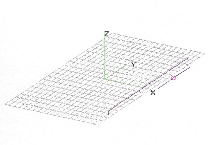
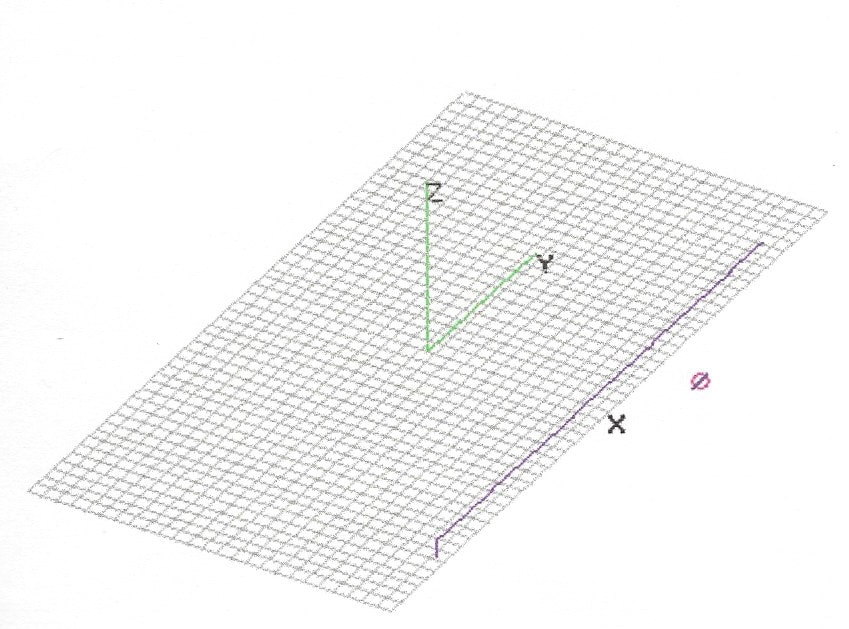
The 4NEC2D program was used to predict the E field at the center of the conductor and 0.5 m above the ground plane. Also the current down the conductor and in the termination of the conductor to the ground plane. Based on the ratio of the 200V/m and the MOM predicted E field the cable and termination currents have been corrected for 200V/m. Figure 1a shows the S/C termination current and Figure 2a shows the cable current.
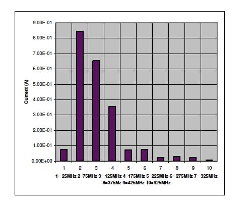
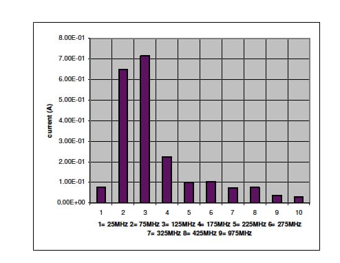
The cable current and voltage induced into a two-conductor line, where one line is terminated to the ground plane and the second line terminated in either 50 Ohm or 1,000 Ohm, was computed. This represents an unshielded signal or control line with 50 Ohm or 1,000 Ohm C/M impedance or the input impedance for signals with the return referenced to chassis. The voltages developed across 50 Ohm for the 200V/m incident E field is shown in Figure 3 and for 1,000 Ohm in Figure 4.


Table 1 shows also shows the voltages.

Clearly, for many signal interfaces, a signal line filter will be required. Reference 1 describes the design and implementation of a large number of such filters.
Voltage Developed into a Shielded Cable at 200V/m
As current flows down a shielded cable, a transferred voltage is developed on the center conductor/s. The voltage is developed across the transfer impedance of the cable. Two common cables used in military and avionic equipment are a single braid with high optical coverage and a double braid with high optical coverage. Assuming the cable shield is terminated at one end to the ground plane, the cable current will be that shown in Figure 5.

Reference 1 shows data on single braid and double braid cable from 100 kHz to 20 GHz.
Table 2 shows the current with the transfer impedances of the cables and the transferred voltages.
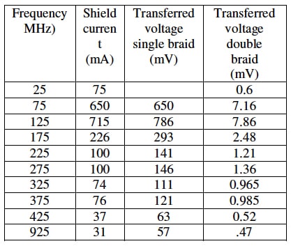
The values in Table 2 are based on well-shielded cables, and assume the transfer impedance of the connector and EMI backshell are very low. When these are not the case then the transferred voltages may be much higher.
If the cable shield is terminated in a pigtail, then the shielding effectiveness may be much lower and the transfer impedance higher as shown in Reference 1. A secondary effect that may be overlooked is that a voltage will be developed between the ground plane due to the inductance of the pigtail. This voltage will be capacitively coupled between the shield and center conductor/s of the shielded cable, which, if the conductors are referenced to chassis or have an impedance to chassis, may result in EMI.
Voltage Developed at the Input of a Power Line Filter
Very often the requirement for input power lines is that the lines must be unshielded. Often isolating converters are used, in which case the power line and return are isolated from chassis, and this isolation is also commonly a requirement. The current induced and the voltage developed due to the incident field is thus C/M.
A very good practice is to include low-value capacitors between the power line and chassis and the power return and chassis at the location where the power enters the enclosure. A good value for the capacitors is 1,000 pF.
Assuming 0805 surface mount 1,000 V capacitors connected to a double-sided PCB with a single via connecting the power line side to the chassis side of the PCB, the total combined capacitor parasitic inductance and via inductance is approximately 3.0 nH. Based on the short circuit current, the voltage developed across a 1,000 pF capacitor is shown in Table 3.
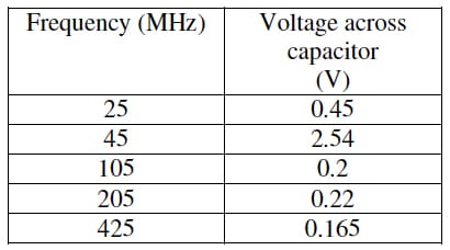
Most power line filters are designed to reduce conducted emissions and are not effective at reducing radiated emissions above a certain frequency. The main purpose for the 1,000 pF capacitors is to reduce the C/M current on the cable, and, thus, the radiated emissions and this has been shown to be effective.
Conclusion
This article provides the predicted voltages developed into cables with an incident 200 V/m E field. An analysis of the effect on the interface circuits can then be made using a tool such as SPICE. Alternatively, a breadboard of the interfaces can be made and common laboratory equipment used to test the immunity of the circuits.
Reference 1
Electromagnetic Compatibility Methods, Analysis, Circuits, and Measurement. David A. Weston. CRC press. 2017


