Molex introduces a versatile selection of EMI-filtered interconnects and RF components, enhancing signal integrity and electromagnetic compatibility for critical aerospace and defense systems. Explore over 250 customizable configurations engineered for optimal reliability in challenging environments. New product portfolio with more than 250 configurations and countless … [Read more...]
Some of the Many Stories of Medical EMI
Introduction I have been collecting stories about EMI for a long time, publishing many of them in the ‘Banana Skins’ column of The EMC Journal, www.theemcjournal.com. Some come from official reports, some from anonymous whistleblowers, some are amusing, and some concern deaths and injuries. At the present time, I have published 855 of them, all indexed by application and by … [Read more...]
Can 5G Sites Be Good Neighbors?
Baseball Hall of Famer Yogi Berra was notable for his skill on the field and was equally notable for many of his quotes. “Yogi-isms” were things he often said that were both amusing and insightful. Referring to a popular restaurant, he said, “Nobody goes there anymore; it’s too crowded.” Sounds like a contradiction, but it’s easy to follow his meaning. Customers chose not to … [Read more...]
Drag Races, a Cashless Society, and the Threat of EMP
About a month ago, my 12-year-old son and I made his first-ever trip to the NHRA Drag Races near our home. It’s something that I always did with my dad, and I have looked forward to taking him ever since he was born. It’s a typical father-and-son day, wrought with loud, fast cars, terrible food, and the occasional waft of nitromethane fuel in the air. The drive is about … [Read more...]
Essential Performance for Medical Products
Introduction Essential Performance has been a mysterious term ever since its introduction in International Standard IEC 60601-1-2 in 2001. Essential Performance is not unique to IEC 60601-1-2, but originates in the general standard, IEC 60601-1, and is used throughout all the collateral and part 2 standards of the IEC 60601 family of standards for medical electric equipment, … [Read more...]
Design for Compliance Essentials
INTRODUCTION While unrealistic to discuss all aspects of product design in a single article, I’ll try to describe the most common design issues I find in the hundreds of client products I’ve had a chance to work on. These issues generally include PC board design, cables, shielding, and filtering. More detailed information may be found in the Reference section below. As … [Read more...]
Filter Installation Issues Pt. 3: Mounting and More
This article is the 3rd and final part of a three-part Filter Installation Issues series. Read Part 1: Input and Output Conductors here. Read Part 2: The Synergy of Filtering and Shielding here. There are now many suppliers of PCB-mounted shielding-cans that can be used with three-terminal filters, and they have many types that can be automatically assembled like any … [Read more...]
Filter Installation Issues Pt. 2: The Synergy of Filtering and Shielding
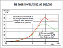
This article is part 2 of a three-part Filter Installation Issues series. Read Part 1: Input and Output Conductors here. Some mains filter manufacturers only design and specify their filters to provide attenuation over the frequency range of the conducted emissions tests (typically up to 30MHz for commercial and industrial products), to keep costs low. Unfortunately, if … [Read more...]
Use of Ferrite-Loaded Absorber to Reduce Wireless Self-Interference
Self-generated EMI from DC-DC converters, as well as digital and video processing, has long plagued designers of wireless and IoT devices, especially since physical sizes have trended smaller. The broadband harmonic content often extends up through 1.5 GHz, which includes most wireless protocols, cellular LTE and GPS/GNSS bands. One new mitigation technique I’ve been trying … [Read more...]
Filter Installation Issues: Input and Output Conductors
Real-life filter performance is totally dependant on how they are installed, especially on the impedance of the RF Reference and the impedance of the method used to electrically bond the filter to its RF Reference. Not only should these impedances be much lower than that of the shunt capacitors in the filters, they should also allow the internal and external CM surface currents … [Read more...]
- 1
- 2
- 3
- …
- 77
- Next Page »


