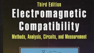
Electromagnetic Compatibility - Methods, Analysis, Circuits, and Measurement, David Weston, CRC Press, 2017 (3rd edition) While I've reviewed many books on EMC, this one by David A. Weston, is the most complete in coverage yet. The 1157-page book covers not only basic and advanced theory of EMC, but includes product design, commercial and military measurement techniques, and … [Read more...]
2017 DoD E3 Program Review – After Action Report
By Brian Farmer on behalf of the DSO E3 Program Review Team After a five-year hiatus, the 2017 Department of Defense (DoD) Electromagnetic Environmental Effects (E3) Program Review was held April 3 - 7 at Lackland Air Force Base, San Antonio, TX. Over 60 technical presentations were delivered throughout the week, three working groups were convened, 12 exhibitors displayed … [Read more...]
The Importance of Layout in ESD Suppressing Diodes
ESD protection of sensitive electronics via transient voltage suppression (TVS) diodes is becoming a common circuit technique across industries. Signal lines in a circuit that are accessible to humans by touch (such as USB, HDMI, etc.) require ESD protection on all sensitive signal lines that are input to some IC’s. Placement of the ESD protection diodes on the circuit board … [Read more...]
Measuring Common Mode Versus Differential Mode Conducted Emissions
When faced with excessive conducted emissions from switching power supplies, one of the first things to investigate and to determine the adequacy of is the power line filter. Line-powered switching supplies generally have both common mode and differential mode sections of the filter as shown in the generalized schematic in Figure 1. When using a line impedance … [Read more...]
ESD Effects of Digital ICs
One issue I see fairly often with unshielded consumer or commercial products is CPU resets during periods of immunity testing, such as during electrostatic discharge (ESD) testing. Untreated, this can lead to field failures and associated customer satisfaction issues. The remedy is usually quite simple and IC manufacturers even mention the solution, but it’s usually buried … [Read more...]
Energy Harvesting is Not Fiction Anymore
“About what we did dream today, are the ideas from tomorrow. The tomorrow ideas are the products from the days after tomorrow.” Our environment is changing and everything is becoming “electronified”. Our glasses, our hand gloves, shirts, shoes etc., can be connected already today with our smartphones and can send commands to the machinery surrounding us. We want this comfort, … [Read more...]
Narrowband Versus Broadband Harmonic Signals
Radiated and conducted emissions measurements are often comprised of both narrowband and broadband sources. So what differentiates “narrowband” and “broadband” signals? Narrowband Versus Broadband Signals The definition of whether a signal is narrowband or broadband as measured using a spectrum analyzer, depends entirely on the receiver bandwidth (resolution bandwidth, or … [Read more...]
Troubleshooting EFT
EFT Phenomenon Recently I tested a medical device for EFT susceptibility. The requirement is that the medical device must be immune to EFT bursts generated per IEC 61000-4-4. Per this standard EFT bursts are applied in four steps. For level 4, steps 1 and 2 are +/-2kV at 5kHz, and steps 3 and 4 are +/-2kV at 100kHz. For each step, these bursts are applied at 300ms interval for … [Read more...]
Gaps In Return Planes – Bad News for EMI
Currently, there is an ongoing discussion among SI and EMC engineers on the fine points of PC board design for best signal integrity and EMI performance. Among the topics it seems designing in gaps or slits in ground return planes always comes up. Gaps can also occur mistakenly due to the addition of some connectors or other object that creates gaps in the copper. In fact, … [Read more...]
T-Filters, Transmission Lines and EMC
Have you ever had a signal integrity issue that did not have its toll on EMC? If you did then you should consider yourself lucky to have avoided this nightmare. I. Situation: An I2S bus master clock driver is set to 12.288MHz and run at 3.3V. Drive strength is at 50-Ohms. Rise time is at 2ns. Fall time is at 2ns. The driver is located on the “master board” and the bus … [Read more...]
- « Previous Page
- 1
- …
- 13
- 14
- 15
- 16
- 17
- …
- 27
- Next Page »


