The effective utilization of power line and ground filters can solve complex EMI problems.
Philip F. Keebler and Kermit O. Phipps, EPRI Electromagnetic Compatibility Laboratory, Knoxville, Tennnessee, USA
INTRODUCTION
With today’s increasing number of electromagnetic interference (EMI) problems, new types of solutions are needed to continue providing compatibility between today’s complex electromagnetic environment and electronic loads. Solutions like advanced power-line filters and very simple ground filters will become increasingly popular EMI solutions as they demonstrate continued effectiveness, especially in situations where other options such as the movement of power lines and large banks of equipment are significantly more expensive than the purchase and installation of a filter or two.
Grounding systems were put into place to provide a safe path for electrical return current thus preventing a severe shock to an unfortunate human. With today’s noisy electrical and electronic equipment, grounding systems also provide a sink for noise current—a way to divert that current away from the equipment that generated it. Diversion of noise current from non-linear loads such as adjustable speed drives (ASDs) and electronic lighting systems is not always directly into the earth. Unfortunately, some parts of all noise current from each non-linear load will try to flow into the ground of other equipment on the same ground. This unwanted flow takes place because some equipment provides a susceptible path for noise current at specific frequencies. In other words, no one piece of equipment will reject noise current at all frequencies. It just so happens that at some frequencies, these noise currents create EMI problems that cause equipment malfunctions, customer complaints, and real customer dissatisfaction. This article provides three case examples of how common EMC practice combined with the use of ground noise filters has solved complex EMI problems.
CASE STUDIES
Case 1: Noise from Multiple ASDs Corrupts Cable Test System
A popular manufacturer of electrical cables used for high-voltage overhead and underground cabling systems installed a new production line for a new type of cable. The new line utilized a variety of adjustable speed drives to control the raw cable materials (two 1-horsepower ASDs), the heating and extrusion process (two 400-horsepower ASDs), and the cable take-up reel (two 1-horsepower ASDs). The size of the line was such that the distance between the ASDs was significant. The two ASDs used to control the heating and extrusion process were closest to the large electrical sub-panel that provided power to the production line. The two ASDs that controlled the unwinding of the raw materials were next, followed by the two ASDs that controlled the take-up reel. The line power for the two large ASDs (400 h.p.) was not in a conduit run, but was hung from a cable mounting system on the ceiling. Hence, these cables were long and unshielded.

Before the finished cable on a reel could be shipped to the customer, the it underwent a partial discharge test. A partial discharge test is used to determine any leakage along the entire length of the cable. If the partial discharge test reveals a charge flow of more than five picocoulombs, the cable fails the test. If the test reveals a flow of less than this amount, then the cable passes the test. The availability of the partial discharge test setup in the plant is a vital piece of equipment to ensure that cable reels are shipped on time.
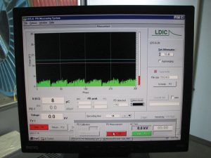
Upon startup of this new production line, use of the partial discharge test setup revealed a problem. As shown in Figure 1, the partial discharge test system revealed a leakage much larger than five picocoulombs. In fact, the test yielded a leakage of almost 40 picocoulombs, eight times the acceptable level. Plant engineers were concerned that the partial discharge test system was not working properly and decided that this system could not be used until someone determined the reason for the unacceptable test results.
In response to the problem, the plant staff began seeking the cause of the erroneous readings on the test monitor. Connections to the equipment were investigated. This partial discharge test system was switched with another one in the plant, and the same problem reoccurred near the new production line. The probe to the partial discharge system was also checked. Cable reels that failed the test at the problem location were taken to the other partial discharge test system and passed the test there. The manufacturer of the partial discharge system was called in, but could not determine the cause of the erroneous readings. A partial discharge test expert was also called in, and still the problem remained unsolved. After several months of investigation, the plant engineer turned to the local utility for some assistance. The local utility called upon EMC engineers to investigate the problem and to determine the cause of the problem.
Investigative Approach
From an overview of the situation, the EMI investigators determined that the coupling mode between the partial discharge test system and sources of ASD noise must be identified. The investigative approach focused on indentifying this mode(s) of the ASD interference sources. Defining the mode of coupling can be very difficult when multiple EMI sources are involved. For example, with an ASD, the source of interference may be conducted and then reradiated and coupled back as a conducted problem or vice-versa. The investigators’ objective is to indentify this source on day one and by day two, to be closing in on the conducted common mode noise source that is causing radiated EMI and partial discharge test set malfunction.
This objective was accomplished through basic empirical methods of carrying out conducted and radiated measurements with a standard spectrum analyzer and associated RF current monitoring sensors and antennas. These measurements revealed that the primary coupling mode from the ASD systems to the partial discharge system was radiated coupling from the unshielded power lines to the ASDs to the probe used in the partial discharge test system. (In the production setup the ground of the probe was connected to the shield of the cable under test, and the positive end of the probe to the center of the cable under test, thus forming a large loop producing radiated emissions from the power lines.)

During the investigation, all aspects of the grounding system were investigated; the power distribution system within the plant was noted; and the configuration of the line, distance, and size of the transformers were considered. Also, the EMI investigators detected the presence of the ASD emissions on the ground system to the ASDs and the ground system to the partial discharge test system including a grounded fence around the test system. Because the emissions were found on several grounded objects, the investigators measured the amount of emissions on the ground conductors to the partial discharge test system and to the ASDs. Because the emissions on the grounded conductors to the ASDs were high, the investigators suspected that lowering these emissions might also improve the performance of the partial discharge test system. The primary solution, however, would involve reducing the coupling between the power lines of the ASDs and the loop area of the probe of the partial discharge test system.
The approach, once the coupling mode was identified, was to apply basic filtering and isolation on a smaller scale to solve the EMI problem. Power line filters combined with isolation transformers were added on the power lines to the ASDs to reduce the conducted emissions traveling down the power line to levels that would no longer couple into the loop area of the probe. Ground filters reduced the flow of conducted emissions through the ground system. Determining the type of filter and its optimal location were yet another critical part of the investigation. Figure 2 illustrates a filter selection box that was designed to provide the EMC investigator with various arrangements of ground noise filters that might be used to solve complex EMI problems.
No investigation is complete without interviewing as many of the individuals that may know something about the problem as possible. Because this problem had been going on for several months and because several other individuals had taken a look at the problem, several round table talks discussing the history and past attempts to mitigate the problem. Failures and successes were recounted, and notes were taken. Through these talks and measurements, the team became even more convinced that the primary mode of coupling was radiated energy from the ASD power line cables to the probe loop. Without these interviews and further knowledge regarding the problem, mitigation techniques might not have been as successful as they were. In addition, knowledge from others about this EMI problem helped the investigators to minimize their time on the site.
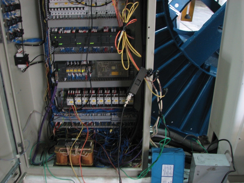
The next challenge and objective was illustrating the concept of the usefulness of the power line and ground filtering and proper isolation for common mode interference. This step was necessary because of the prior attempts the plant staff had made in trying to solve the EMI problem. This was a difficult task to achieve on the 400-horsepower ASD because of the size of the conductors involved, so the 15-horsepower ASD on the take-up reel was chosen as shown in Figure 3. This drive was also closest to the partial discharge system. Drawing upon the EMC team’s experience in working with the IEEE 1560–Standard for Methods of Measurement of Radio-Frequency Power-Line Interference Filter in the Range of 100 Hz to 10 GHz and associated EMC filter work in the past, the team was able to demonstrate this concept on the smaller source of interference.
The Solution
The nature of this EMI problem warranted more corrective action than simply bringing the test results below an acceptable five-picocoulomb level. One aspect of the problem that was not a viable solution was the relocation of the test system or the new production line. It just so happened that they were adjacent to each other. The three solutions that were investigated are discussed below.
On the assembly line, there were two 400-horsepower ASDs and two 15-horsepower ASDs. Each ASD was identified as a source of interference. These emissions sources were confirmed in short order because of the magnitude of the interference at the partial discharge test system.
Early attempts were made to screen the area in the test cage where the probe was used. Unfortunately for this customer, an earlier EMC investigator had recommended the building of a Faraday shield. The shield specifications including the mounting of 1/0 stranded copper bare conductor combined with three-quarter foot copper water pipe on 4-foot centers around the test cage area. As most of us know from shielding theory, this approach is ineffective for shielding electric fields, and the customer’s money and time had been wasted.
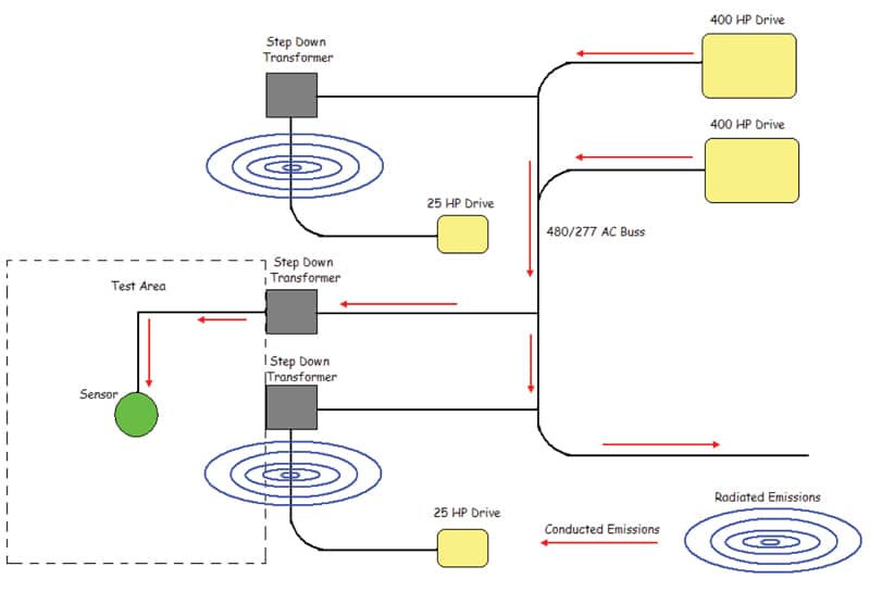
As seen in Figure 4, the conducted path was due to the large horsepower drives conducting emissions on the 480-volt AC buss, which ran parallel to the assembly line in close proximity to the partial discharge test system. As mentioned earlier, the measured emissions found on the power source at the probe in the test cage area indicated a conduction problem. Radiated fields carrying the signature of the 15-horsepower drives were also measured at the probe and no doubt resulted from the conducted emissions found on the 208-volt AC step-down transformer. Given the magnitude of the high frequency currents, relatively large radiated fields were generated by 15-horsepower drive at the bottom of the Figure 4. Fields generated by an identical drive located at the top of the diagram were found to be less of a concern because of the distance from the partial discharge test system.
Reducing the Emissions from the Drives
Because the emissions and physical characteristics of each drive (noise source) were different, the basic approach to the problem was to consider discrete steps to determine the optimal solutions for each drive. First, attention was focused on the largest interference source, the 400-horsepower ASDs. All systems were shut off, and only the 400-horsepower drives were left running.
Conducted measurements were performed throughout the facility, and it was determined that the voltage was being slightly distorted by the current drawn from the drives. In general, power quality measurements would not have detected these distortions as they might not have been of significant amplitude and hence immeasurable. But with high frequency monitoring probes, the high frequency components of the ASD were measured with a spectrum analyzer. These measurements indicated a relative soft source, but the actual problem was due to the impedance mismatch of the 480-volt AC, 60-Hz power system.
These minor differences in impedances affected the operation of power line filters internal to the ASDs. It was determined that the drive manufacturer had specified an isolation transformer as part of the original installation to ensure proper ASD operation and to reduce interference problems. Unfortunately, the contracting firm that installed the drives recommended not using the transformer to save costs because the ASDs had built-in power line filters. While this was true, the isolation transformer being installed in close proximity to the ASDs would have resulted in a lower impedance vis-à-vis the filters, which had been designed to provide better impedance match. A second, but not often understood benefit of a transformer, not necessarily an expensive isolation rated transformer, is its ability to reduce the return ground loop area for conducted emissions and to prevent them from circulating throughout the building ground system and causing incompatibility issues with other equipment.
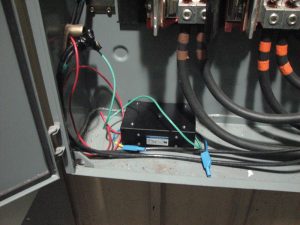
Measurements were performed at the area of the partial discharge system where the probe was used after the installation of the isolation transformer (not shown). The interference had been reduced to near acceptable levels from the 400-horsepower ASDs. In addition, a 20-amp ground noise filter was installed on the subpanel feeding the 400-horsepower drives as shown in Figure 5.

The next area of focus was the 15-horsepower ASDs. Measurements were performed on the line input to the ASD nearest the partial discharge test system, and a custom designed filter had to be manufactured and installed. The manufacture of the filter worked with the investigation team to design a filter that would be suitable for use on these ASDs as shown in Figure 6. Too much inductance would create other power quality issues, such as nuisance tripping caused by low DC link voltage conditions inside the drive making the equipment more susceptible to sags.
After the EMC investigator left, the filter was installed by the electrical contractor at the step-down transformer; however, interference problems still occurred. Upon a re-examination of the filter installation, the EMC investigators quickly realized that the contractor had not followed the guidelines provided by the team. To control the radiated and conducted emissions, the filter must be installed directly at the drive (as close to the input terminals as possible), and the transformer must be located next to the filter to ensure proper emissions attenuation. Again, there was the troublesome issue of the impedance with long cable runs between the power source and the power line filters. Once corrective actions were taken, the interference was reduced and found to be at acceptable levels with all systems operating as shown in Figure 7.

Application of a 5-amp ground noise filter on the ground line of the 15-horsepower drive resulted in a reduction of noise emissions on the ground line as shown in Figure 8. The emissions reduction, which was as much as 30 dB, also reduced the background noise on the partial discharge system.
Summary
The combined radiated-conducted emissions from each of the drives in the plant affected the background noise level of the partial discharge system. The noise level was too high for the two to coexist without some mitigation measures. Even if the original installation of the 15-horsepower drive closest to the partial discharge system had contained an isolation transformer and second power line filter adjacent to the drive, the noise from the other drives would have rendered the test system non-usable. Inspection of the plant area, including the partial discharge test system, prior to the installation of the new cable manufacturing assembly line might have revealed this issue. Still, the key factor that might have helped avoid this problem would be the basic realization that partial discharge systems are indeed sensitive to emissions from devices such as drives. Shorter main conductor runs to the drives would also have helped.
CASE 2: QUIETING DOWN FOR ELECTRONIC HID LIGHTING
The Situation
High-frequency electronic lamp-ballast systems are being used more frequently in commercial and industrial facilities to provide a source of energy-efficient fluorescent and HID (high intensity discharge) lighting. Lamp and ballast manufacturers have designed many of these systems to provide high-efficiency lighting systems. A college recently installed universal-voltage electronic HID ballasts in the gymnasium where basketball games were played. These high-efficiency electronic HID ballasts were installed to replace existing 400 watt high-pressure sodium (HPS) magnetic ballasts. After a 100 percent replacement of ballasts to alleviate component-related ballast failures, the ballasts continued to fail. Following limited power quality monitoring efforts by a consulting organization, the fixture manufacturer and the ballast manufacturer suspected that there could be wiring and grounding issues within the facility. Failure of fixtures and ballasts in the gymnasium rendered the basketball court unusable if the light levels became too low. Repair of the fixtures and ballasts started to become a regular task before weekly basketball games could be played.
Our objective was to conduct a detailed on-site investigation to determine if there were wiring and grounding issues present at the college facility where these failures occurred with such frequency. We conducted a two-day on-site investigation of the wiring and grounding system that provides power to the lighting branch circuits used to power the ballasts.
Investigative Approach

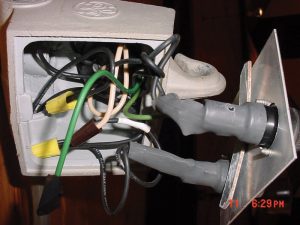
The wiring and grounding system in the arena was checked carefully by power quality/EMC investigators. The investigation revealed that the ground conductor inside the wiring box where the fixtures were wired to the building electrical system had not been connected to the fixture ground. The investigators determined that because this ground (as shown in Figure 9) had not been used when the magnetic HID fixtures were installed, then it was omitted once again when the electronic HID fixtures were installed. (Electronically-ballasted lighting systems require a solid ground connection to help ensure protection against voltage surges (if surge protectors are used within the ballast to ground) and to provide a sink for conducted line emissions from the internal power-line filter.) Without this ground, electronic lighting systems are at a higher risk of failure.)
In addition to identifying the non-connected ground inside the wiring box where the electronic HID fixtures were connected, high-levels of ground noise were found on the panel providing power to the HID lights. Inspection revealed that one of the main buses providing power to this panel also provided power to another panel that served ASDs that were used in the heating-ventilation-and-air-conditioning system (HVAC) for the gymnasium. To isolate the noise on the ground for the ASDs and to keep it from the ground for the electronic HID lights, a 5-amp ground noise filter was recommended for installation at the panel as in Figure 10. (A 5-amp filter was temporarily installed (at the green dot) in this panel to demonstrate proof of concept.)
Emissions Reduction at the Lighting Panel
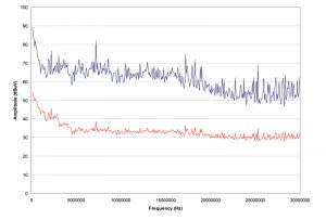
Because the level of conducted emissions was high at the ground within the panel, the investigators elected to install a 5-amp ground noise filter on the panel’s main ground conductor. The installation of this filter would reduce this level of emissions and would help separate the ground of the lighting panel from the ground of the ASD panel. Figure 11 illustrates the level of conducted emissions on the ground of the lighting panel prior to the installation of the 5-amp filter (top graph) and after the installation of the filter (bottom graph). As one can see, the reduction of emissions is approximately 20 to 30 dB depending upon frequency.
CASE 3: EXTERNAL NOISE CURRENTS INTERRUPT CRITICAL OPERATIONS AT A BUILDING MATERIALS DISTRIBUTION CENTER
The Situation
A major building materials distribution company supplies construction projects throughout a large sector of the building industry. In fact, this entity has become the largest single source provider of environmental remediation, construction, packaging, and janitorial products in the Western United States.
The building materials company experienced serious unusual and unexplainable malfunctions of end-use electrical and electronic equipment and of power distribution equipment such as circuit breakers of various sizes and their uninterruptible power supplies (UPSs). Such malfunctions had interrupted power to building loads, telecommunications, Internet traffic, server operation, and the operation of the fire alarm system.
Investigative Approach
Experienced field investigation engineers in the areas of power quality and electromagnetic compatibility traveled to the building materials company to investigate:
- Equipment Upsets: Engineers evaluated the upset of all end-use equipment at the facility. The evaluation encompassed inspection of equipment performance, installation, and type of malfunction to determine which specific measurements should be conducted at the equipment on site. The results of such measurements were used to spot telltale connections between the malfunctions and the mechanisms that may have caused the problems.
- Electromagnetic Environment: Engineers conducted selected radiated and conducted electromagnetic environment tests to determine the characteristics of the electromagnetic environment both inside and outside the facility. The area of coverage for the outside measurements was determined at the site. These measurements included both electric and magnetic fields up to 1 GHz for selected fields. Engineers utilized their advanced shielded emissions measurement system to record and to analyze data captured at the site. This system was designed specifically to investigate complex electromagnetic problems such as those disrupting the building materials site. Because the facility was very close to a high-voltage DC power line and to its inverter station, several conducted emissions measurements were taken on ground conductors, power conductors, telephone and network Internet conductors, and steel beams.
- Electrical Environment: Engineers conducted selected electrical environment tests to determine the characteristics of the electrical environment inside the facility. Selected measurements probed further into the facility’s electrical system, and investigators made additional measurements that had not been taken in the past. The results of such measurements were used to link the upsets to the mechanisms and the cause of the problems.
Reducing Emissions on the Telephone, Network, Internet Communications System, and UPSs
Because the EMC investigators determined that emissions from the outside electrical environment were getting into the facility electrical and telecommunications system, they decided to use ground line noise filters that would reduce the ground emissions and would improve the performance of the facility’s equipment.
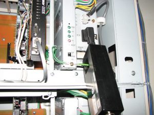

Figure 12 illustrates the power supply unit and associated power switch for the telecommunications equipment at the facility. The switch shown here is in the “on” position, and all green LEDs indicate that the system is working normally. Still, the power supply for this telephone switch would intermittently fail and would need to be reset by operating the power switch. A 5-amp filter was installed (behind the cover) on the frame of the phone switch in the ground conductor to the power supply. The use of the filter in the ground line reduced the conducted emissions allowed to flow into the switch as shown in Figure 13.

Figure 14 illustrates the high-speed communications circuitry that supports the company’s business activities. This provides personnel access to the Internet and the outside world. The original location for this system was at the telecom switch. Because of the on-going issues with equipment damage and upset it was moved to this location, which is about 20 feet from the previous location. The three small circuit cards at the bottom of this equipment set provide status indicators as to the function of the connection. During times of lost connectivity, the system would enter into a ‘test’ mode or ‘loop’ mode. Reset to the normal mode would require human intervention by depressing a reset button on each card.
After the conclusion of the power quality audit, the customer set out to purchase and to arrange for the installation of a new ATS and UPS with a new transfer switch and a larger capacity emergency generator. After this installation, they reported that the standby generator installation was scheduled for a final inspection in April 2008. The local electrical inspector insisted upon the installation of a grounding conductor on the standby generator installation. The inspector insisted that the UPS in the phone room be bonded to a grounding electrode. Thus, the customer contracted with an electrician to run a No. 6 AWG grounding conductor for each UPS up to one of the main steel beams in the ceiling of the facility. After the installation of these ground conductors, transients started showing up immediately on a power quality monitor that was connected to the feeders of the fuse panel fed by the generator ATS. The only loads on that panel were the two single phase 6-kVA UPS units and the server room single-phase heat pump. None of these transients appeared to be related to the on/off cycling of the heat pump. At any rate, the customer reported that it does appear that bonding to the beam has created a ground loop that is allowing transients to pass to the panel. The customer contacted the UPS manufacturer and questioned the ease by which transients and noise could pass through the UPS to its output.
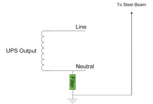
To help prevent the circulation of ground noise currents in the output circuit of each UPS, ground noise filters were installed as illustrated in Figure 15. The ground filter will block noise currents that try to enter the neutral circuit from the steel beam or from the electrical ground on the output of the UPS.

Ground noise currents may also enter the input of a UPS and could cause UPS upset. To help prevent against this malfunction, ground noise filters can be installed on the UPS inputs as well. See Figure 16.
Summary
After the customer implemented the recommended changes to the wiring and ground system (including the installation of the ground noise filters), the equipment malfunctions and dropped telephone, network, and Internet connections were eliminated. These filters, combined with the wiring and grounding changes, helped to isolate the customer’s facility and equipment from noise from the outside electromagnetic environment.
THE FILTER TECHNOLOGY
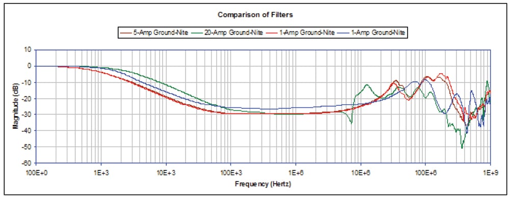
The ground noise filter is a patented technology essentially comprised of a specially designed core with a few turns of solid copper wire wrapped around the core, all in parallel with a resistor. The core and turns provide an inductive impedance to the ground impedance connected to the filter. Although the filter technology is simple, it has been shown in many examples to resolve ground-related EMI problems. To determine its effectiveness and ability to withstand electrical disturbances that commonly travel through ground circuits, we conducted a series of tests on the filter technologies. In this instance, a 1-amp, 5-amp, and 20-amp filter were tested. Figure 17 illustrates the results of one of fifteen tests conducted on each filter model. This test is quite significant as it illustrates the baseline attenuation performance that each filter can provide. One can see that the attenuation performance is approximately 30 dB from about 100 kHz to a few MHz. Other tests illustrated the expected minimal degradation in attenuation performance caused by differences in ground impedance and steady-state ground current.
CONCLUSION
The three case studies that have been presented and discussed above illustrate the effectiveness of utilizing power-line and ground filters to resolve complex EMI problems. This technology and application is beginning to show the combined effectiveness of using power-line filters with ground filters in resolving various types of EMI problems. Engineers and consultants fail to recognize that ground systems are the one electrical system common to all sources and loads, and that grounds often provide a means for emissions current from one piece of equipment to flow to another, creating an EMI problem. It should also be noted that the application of better power-line filters and ground noise filters should not be considered as “solve-all” technologies for EMI problems. Still, the better prepared EMC investigator should start focusing more on grounding systems, how they might be providing that path for EMI problems, and the effects of using ground noise filters to ‘interrupt’ that path— especially at those frequencies of interest where so many EMI problems occur.
ABOUT THE AUTHORS
Philip F. Keebler has conducted System Compatibility Research on personal computers, lighting, medical equipment, and internet data center equipment. The lighting tasks were associated with characterizing electronic fluorescent and magnetic HID ballasts, electronic fluorescent and HID ballast interference, electronic fluorescent and HID ballast failures, and electronic fluorescent and HID lamp failures. He has drafted test protocols and performance criteria for SCRP tasks relating to PQ and EMC. Mr. Keebler also manages the Electromagnetic Compatibility (EMC) Group at EPRI where EMC site surveys are conducted, end-use devices are tested for EMC, EMC audits are conducted, and solutions to electromagnetic interference (EMI) problems are identified. He has completed his service as editor developing a new EMC standard for power line filters, IEEE 1560.
Kermit O. Phipps is a NARTE Certified EMC engineer and conducts tests and evaluations of equipment performance in accordance with the standards of ANSI/IEEE, IEC, U.S. Military, and UL, as well as with the EPRI System Compatibility Test Protocols for EPRI. He served in the U.S. Air Force as a manual electronic warfare and component specialist, resolving hardware and software problems. He conducts research on surge protection, power line filters, shielding effectiveness, and electromagnetic interference. Mr. Phipps is the author and co-author of test plans, protocols, and research papers presented at international power quality and EMC conferences. He has conducted a number of power quality and EMC training sessions and field investigations. Most recently, he has completed his voluntary work as chairman in developing a new EMC standard for power line filters, IEEE 1560.


