By Krzysztof SIECZKAREK1, Adam MAĆKOWIAK1
1Institute of Logistics and Warehousing, Laboratory of Electronic Equipment, Poznań, Poland, LA@ilim.poznan.pl
Abstract: The aim of this work was to create an application dedicated to the automatic verification of test equipment used in electromagnetic compatibility testing. In order to perform it the LabView programming environment was chosen – a versatile tool with a graphical programming language. This paper presents the normative requirements analysis, LabView environment outline and description of created software.
Keywords: EMC, equipment verification, transient signals, burst, surge, LabView software.
Introduction
The operation of an accredited laboratory dealing with electromagnetic compatibility testing requires necessity of periodic verification of test set-ups. For the sake of quite big amount of parameters to check such verification is time-consuming and needs a good knowledge of testing equipment (for instance digital oscilloscope) both in the range of its maintenance and protection as well as in the scope of fitting the measurement paths into the high-voltage signals. For these reasons Institute of Logistic and Warehousing decided to create such a tool for automatic verification which will minimize personnel participation in periodic verifications and short its duration.
Within this work there were made applications to automatic verification of:
- electrical fast transient/burst immunity test equipment,
- surge immunity test equipment,
- pulse magnetic field immunity test equipment.
Normative requirements
Surge immunity test
Test methods and immunity requirements of electric equipment subjected to surges are well described in International Standard [1]. This standard gives also specification and requirements for test generators and voltage waveforms. The values for the different components are selected so that the generator delivers a 1,2/50 ms voltage surge (at open circuit conditions) and a 8/20 ms current surge into a short circuit.
The real waveform of “1,2/50 ms” open-circuit surge voltage is shown in figure 1. The summary requirements for surge generator verification are given in table 1.
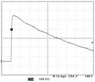
Table 1. Requirements for surge generator verification.

Test methods and immunity requirements of electric equipment subjected to transient disturbances are described in International Standard [2]. This standard gives also specification and requirements for test generators and voltage waveforms. Real graphs of a fast transient are shown in figures 2 and 3.Electrical fast transient/burst immunity test
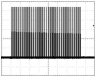
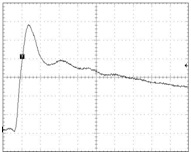
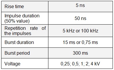
The summary requirements for fast transient/burst generator verification are given in table 2.
Table 2. Requirements for fast transient/burst generator verification.
Pulse magnetic field immunity test
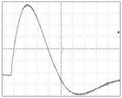
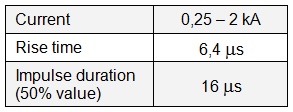
Test methods and immunity requirements of electric equipment subjected to impulse magnetic fields are described in International Standard [3]. This standard gives also specification and requirements for test generators and voltage waveforms. The real waveform of current in induction coil is shown in figure 4.
The summary requirements for impulse magnetic field generator verification are given in table 3.
Table 3. Requirements for impulse magnetic field generator verification.
LabView software
LabVIEW (Laboratory Virtual Instrument Engineering Workbench) is a graphical development environment for data acquisition, analysis, and presentation from National Instruments. Distinct from application like C or Pascal it does not use text-based languages to create lines of code. LabVIEW uses a graphical programming language, G, to create programs in block diagram form. LabVIEW programs are called virtual instruments because their appearance and operation imitate physical instruments, such as oscilloscopes and multimeters. LabVIEW contains a comprehensive set of tools for acquiring, analyzing, displaying, and storing data, as well as tools for debugging.
All LabVIEW programs have a front panel and a block diagram. The front panel is the graphical user interface. This interface collects user input and displays program output. The front panel can contain knobs, push buttons, graphs, and other controls and indicators. The block diagram contains the graphical source code of application. In the block diagram one can program an application to control and perform functions on the inputs and outputs created on the front panel. The block diagram can include functions and structures from the built-in LabVIEW libraries. It also can include terminals that are associated with controls and indicators created on the front panel [4].
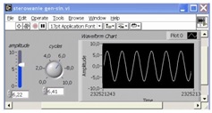
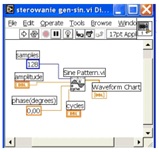
The front panel of basic application generating sine wave is shown in figure 5; its block diagram is shown in figure 6.
Applications
Verification of surge generator
Verification of surge generator was carrying out in set-up shown in figure 7.
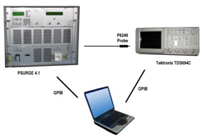
Notebook with LabVIEW software controls the generator and oscilloscope by use of GPIB interface. In order to protect from overvoltage the oscilloscope input was connected to line output of generator through the active probe. An application consisted of three functional parts:
- initialisation,
- configuration,
- data acquisition.
In initialisation part general information how to create the test set-up are shown. After that application checks test equipment and initialises communication.
In configuration part user can set the parameters of the test, such as surge voltage, impulse polarisation, repetition number. On the basis of generator settings an application automatically set the oscilloscope in order to ensure optimal signal sampling and recognition. Oscilloscope can also be set manually. Settings of equipment can be read and write to file.
The main part of application is data acquisition and processing module. After oscilloscope triggering appropriate quantities are measured and shown in application panel. The quantities are shown as presently measured values and as a mean value at given moment of measurement cycle. In panel is also shown recorded waveform (in three different time-bases). Such constructed loop is repeated until it reached number specified by user. Front panel of surge generator verification application is shown in figure 8.
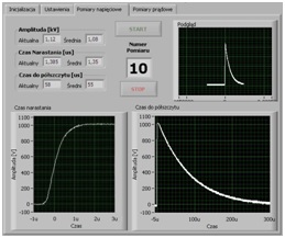
In case of short circuit current measurements the connection between oscilloscope and generator is changed – instead of P6249 probe the current transformer is used. Measuring quantities and front panel arrangement are the same.
Verification of burst generator
Test set-up for burst generator verification is shown in figure 9.
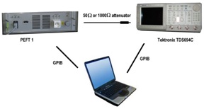
Notebook with LabVIEW software controls the generator and oscilloscope by use of GPIB interface. An application also consisted of three functional parts.
In initialisation part general information how to create the test set-up are shown. After that application checks test equipment and initialises communication.
In configuration part user can set the parameters of the test and select an attenuator. On the basis of generator settings an application automatically set the oscilloscope in order to ensure optimal signal sampling and recognition. Because of big amount of quantities to be measured there is no possibility of manual oscilloscope settings.
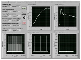
The main part of application is data acquisition and processing module. In order to measure all needed parameters the burst waveform is analysed in 5 different time-bases in one measurement cycle. After oscilloscope triggering appropriate quantities are measured and shown in application panel. Quantities are shown as presently measured values and as a mean value at given moment of measurement cycle. In panel are also shown recorded waveforms. Such loop is repeated until it reached number specified by user. Front panel of burst generator verification application is shown in figure 10.
Verification of magnetic field generator
Test set-up for magnetic field generator verification is shown in figure 11. A notebook with LabVIEW software controls the generator and oscilloscope by use of GPIB interface. Current of induction coil is measured by use of current transformer with divider 1A = 0,01 V.
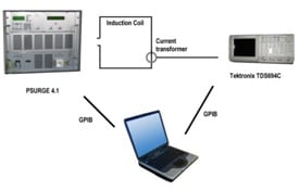
An algorithm, measured values and front panel appearance are the same as in current measurement part of surge verification software.
Conclusion
The aim of work described in present article was to create software for automatic verification of selected equipment used in electromagnetic compatibility laboratory. Three following applications were made:
- software for verification of electrical fast transient/burst generator,
- software for verification of surge generator,
- software for verification of pulse magnetic field generating system.
All above applications were created by use of LabVIEW graphical development environment. The creation of these applications process was at the same time a good test of possibilities of practical LabVIEW application in laboratory. It appears that its versatility, easy of use and big amount of existing libraries make it a suitable tool for electronic equipment controlling. Additionally, creating an application in LabVIEW environment does not need advanced programming skills.
All applications created within this work were put into practice in EMC Laboratory at Institute of Logistic and Warehousing and also are available for other EMC test labs. All of them standing the test of time simplifying the verification process and making it considerably shorter.
References
[1] EN 61000-4-5 Electromagnetic Compatibility – Testing and measurement techniques – Surge immunity test.
[2] EN 61000-4-4 Electromagnetic Compatibility – Testing and measurement techniques – Electrical fast transient/burst immunity test.
[3] EN 61000-4-9 Electromagnetic Compatibility – Testing and measurement techniques – Pulse magnetic field immunity test.
[4] LabView7 Express – Getting Started with LabVIEW, National Instrument, April 2003 Edition.
About Company
 The Laboratory of Electronic Devices of Institute of Logistics and Warehousing carries out the research work and deals with technical assessment in the area of electrical safety and electromagnetic compatibility EMC of electronic and electrical equipment. Laboratory holds accredited quality management system according to EN ISO/IEC 17025. Laboratory is notified by European Commission to act as Notified Body under 2004/108/EC EMC Directive.
Authors
Krzysztof Sieczkarek graduated from Poznan University of Technology in 1994, PhD in 2003. He has been working in EMC test laboratory of Institute of Logistics and Warehousing in Poznan since 1994; present position – laboratory manager. Member of IEEE EMCS, FOR-EMC, IEC TC 77 and CISPR I.
Adam Maćkowiak graduated from Poznan University of Technology in 1997, PhD in 2001. He has been working in EMC test laboratory of Institute of Logistics and Warehousing in Poznan since 2003; present position – technical manager.


