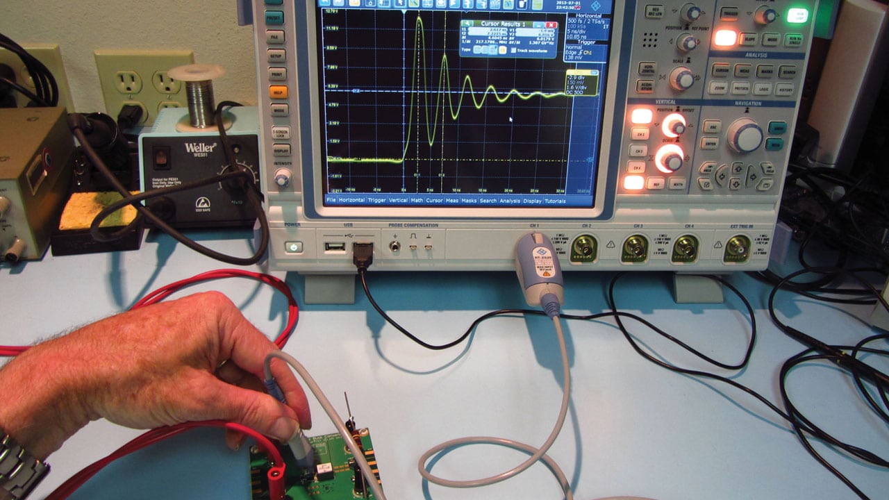
This article concludes the two-part series, Assembling Your Own EMI Troubleshooting Kit – Part 1, which included a listing of the major components of a complete EMI trouble shooting kit that can be easily transported where needed. Most of the probes and tools listed in Part 1 were useful for troubleshooting radiated emissions. In Part 2, we’ll discuss several other useful additions to your kit, including low cost tools for evaluating the most common immunity issues, such as radiated immunity and ESD. As a bonus, we’ll also describe how to use an oscilloscope for EMI troubleshooting.
USEFUL ADDITIONS TO YOUR KIT
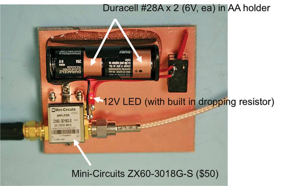
Sometimes the signal level from near field probes needs a boost – especially from the smaller-diameter H-field probes. For this, I recommend a broadband preampli-fier, such as those available from Mini-Circuits (Figure 1), Beehive Electronics, Tekbox, or Aaronia AG. There are many other manufacturers of these from the larger test and measurement companies.
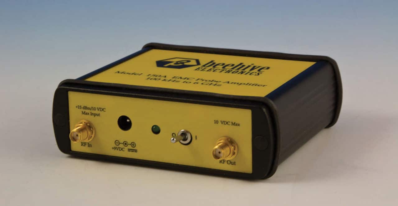
Beehive Electronics also has a nice preamplifier that can be powered from an exterior 9V battery plugged into the power input jack (Figure 2). This makes the unit portable with one less line cord to deal with. The unit has 30 dB of gain from 100 kHz to 6 GHz, which covers all the commercial frequency ranges of interest. The cost is $525 through their website.
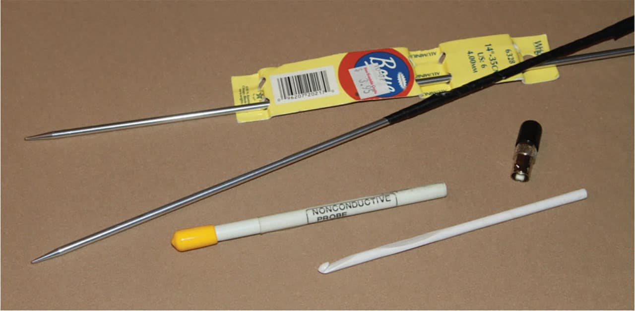
Metal knitting needles may be used as antennas by touching to the circuit board or pins of a connector. Being metal, they will act as an extended antenna. If the circuit connector pin is a source of RF, this may increase when touched with the metal knitting needles. Be sure to insulate the handle end of needle for safety reasons and take care to avoid shorting out circuits.
Plastic knitting needles, crochet hooks, or probes may be used to manipulate wires or press on chassis without having to touch the equipment, which can change its effective radiation (Figure 3).
USEFUL RADIATED IMMUNITY ITEMS
One of the more frequent product failures I see is radiated immunity. That is, the product under test is susceptible to outside RF transmitters. There are a number of low cost solutions to help check the sensitivity of your product to external RF energy.
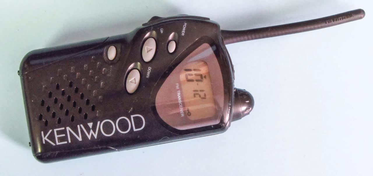
One of the simplest is a small handheld Family Radio Service (FRS) license-free walkie-talkie (Figure 4). These produce about 1/2-watt in the 465 MHz band and may be used to quickly check the susceptibility to RF, in general. Best of all, they sell for about $30 a pair. Just press the transmit button briefly and hold it near your product to see if it induces any upset or instrument lockup. I’ve resolved many radiated immunity problems with nothing more than one of these radios.
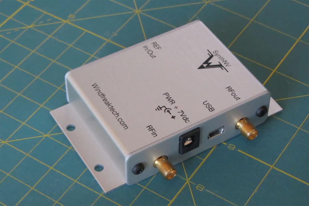
For a more elegant and controlled test, I find the PC-controlled RF synthesizer; model SynthNV, from Windfreak Technologies to be ideal (Figure 5). It will produce up to +19 dBm (90 mW) into 50 Ohms. The unit tunes from 34 MHz to 4.4 GHz in user-defined steps as low as 1 kHz. It can also modulate the RF with AM or pulse modulation, which is useful for commercial or military immunity testing according to the respective standards. The price is $599 from their website.
To perform a quick immunity test with the SynthNV, simply attach the larger size H-field probe to the output and scan the probe around on your circuit board and any interconnecting or I/O cables. Adjust the frequency to step every 50 MHz, or so, for each scan throughout the desired frequency band. For more details, refer to the article, Inexpensive Radiated Immunity Pre-Compliance Testing[1].
Another very effective source of broadband RF emissions is a “chattering relay”. This is actually specified in certain MIL-STD-461 and DO-160 standards. A chattering relay is merely a line or DC-operated relay with the normally closed contacts wired through the coil. When powered, the relay coil opens the contacts, which then deactivate the coil, allowing the contacts to close again. This continues with a loud buzzing sound as the contacts continuously open and close. The inductance of the coil creates a 600 to 800 volt repeated arcing across the contacts. This produces a broadband RF noise spectrum as high as 1 GHz. According the standards, closely coupling the cable of the chattering relay to the product’s power cable, is a rather rigorous immunity test. I find that simply holding the relay near your product circuitry should reveal any issues pretty quickly.
TESTING FOR ELECTROSTATIC DISCHARGE (ESD)
The other frequently encountered EMC issue I find is due to susceptibility to ESD. With the trend towards lower power supply voltages (5V to 3.3V to 1.8V to 1.2V, and lower) is the overall reduction in noise margin for digital circuits. There are a number of low cost tools we can use to evaluate our products for ESD immunity.
Normally, ESD current pulses of up to 8 or 15 kV are applied to any external metal that could be touched by the equipment operator. This would include front panel controls, displays, connector ground shells, metal enclosures, and the like. Exceptions under most ESD standards would preclude testing directly into I/O pins or internal circuitry. I must caution you that this test is potentially destructive, so I usually try to test less sensitive points first and with lower test voltages.
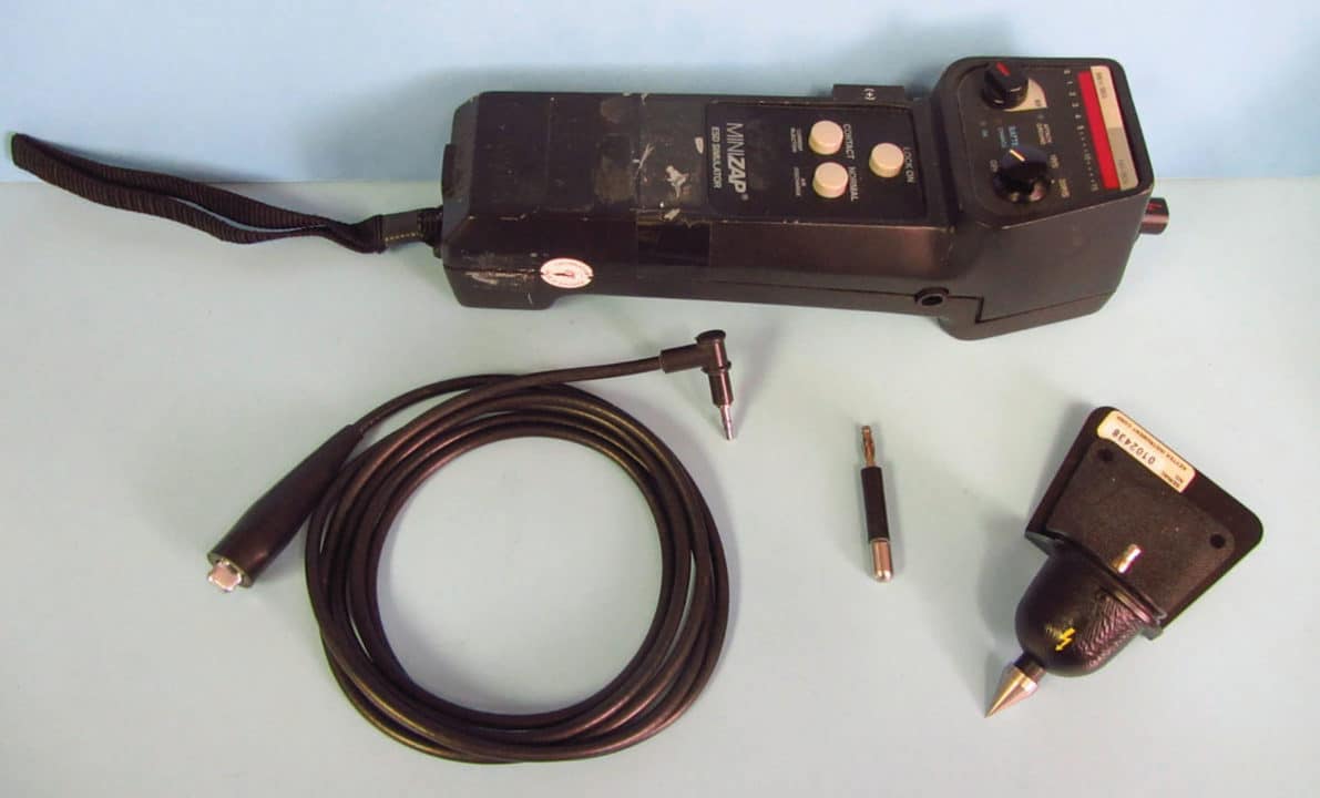
Of course, the best approach would be to use a commercial ESD simulator. I like the KeyTek MiniZap (Figure 6). While new ones can cost about $20k, these may be commonly found in the used market for under $3,000. However, to fit within our $5,000 maximum budget, here are some alternatives that will help characterize the ESD immunity of your product.
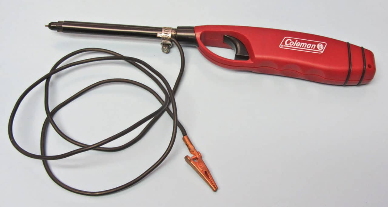
There are various piezoelectric spark sources, such as BBQ lighters, that will produce several kV of electricity. One I like is the Coleman brand butane lighter, because you don’t need to open the gas valve in order to trigger a spark (Figure 7). By carefully removing part of the outer metal shroud with a Dremel tool, you’ll expose the center tip where the arcs originate. Connecting a ground return wire to the metal shroud will complete the circuit. Just place the product under test on a metal-top table (or lay out some aluminum foil to cover the table top as a conductive plane). You’ll need a way for the electrostatic charges to bleed off the metal plane, and you can connect a 1 Megohm resistor from the metal plane to earth. Then, connect the ground return wire to the metal plane, hold the lighter tip within 1/4-inch and start triggering the arcs. This lighter will produce from 4 to 6 kV discharges.
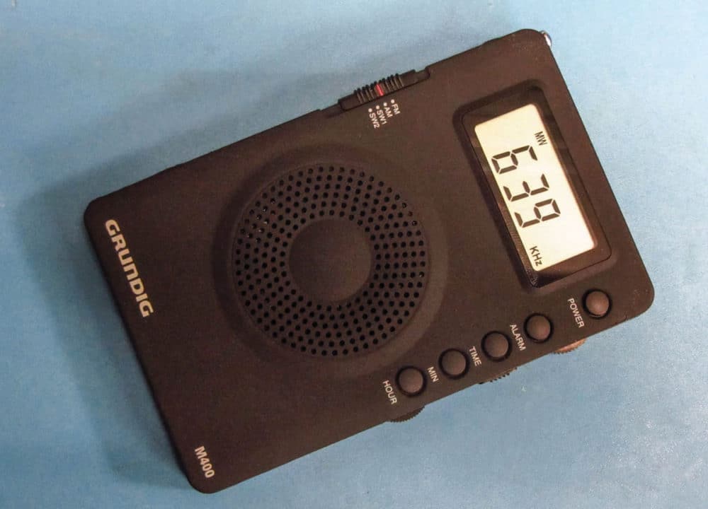
The problem with ESD susceptibility is that it usually occurs in-frequently. Therefore, you’ll also want a way to detect ESD discharges to help indicate when an event occurred. An inexpensive AM broadcast receiver (Figure 8) will make a simple ESD detector. Just tune the radio off-station, so you just hear the background hissing. You’ll be able to hear ESD events as “clicks” in the static. If you’re handy with electronic projects, you can also make the DIY ESD detector and counter found on my personal website. It is based on a popular lightning detector circuit. The construction article may be found under “Technical Articles”. The basic circuit includes the detector and a pulse-stretcher circuit. By adding extra switch transistors, you can add various indicators. Mine will blink a light, beep a buzzer, and also has a digital event counter.
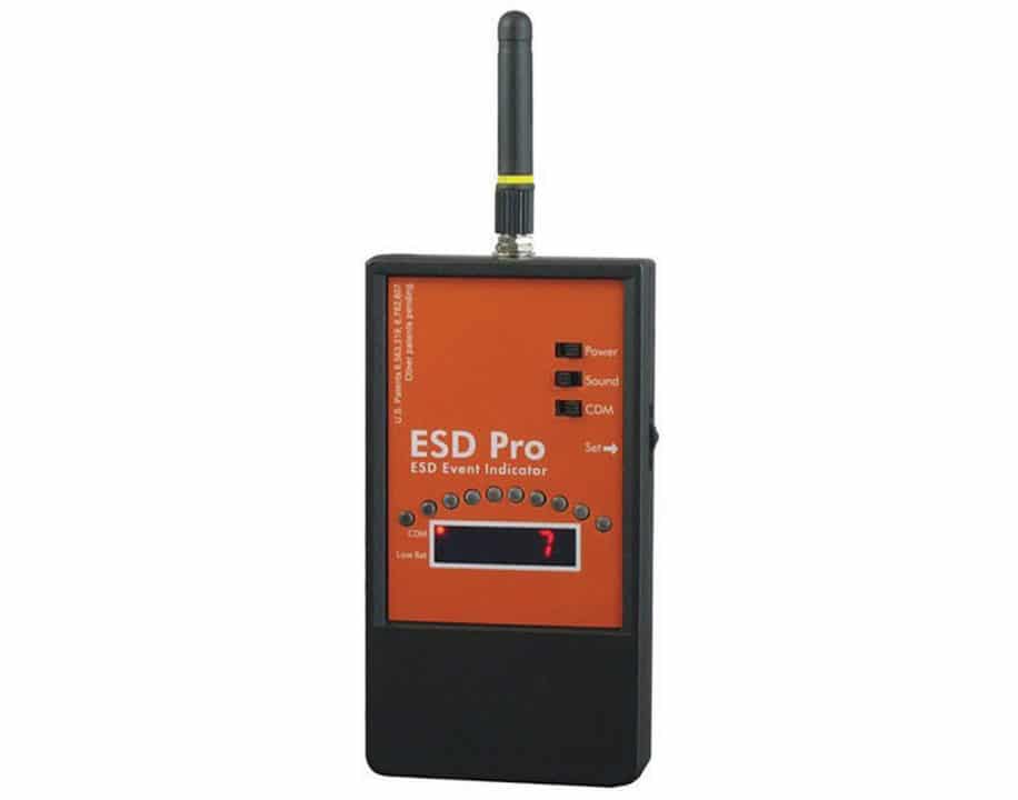
A better commercial tool would include the “ESD Pro” ESD detector (Figure 9), manufactured and sold by Static Control Systems. It is extremely sensitive and will detect ESD from hundreds of feet away.
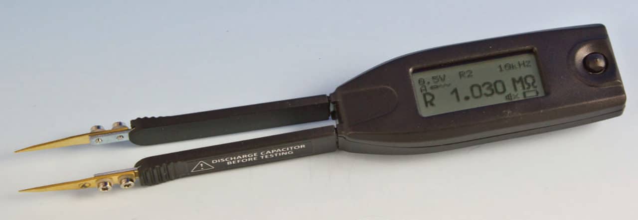
One very useful tool is a SmartTweezer RLC meter from Advance Devices (Figure 10). This small tweezer can help you identify surface mount (or leaded) resistors, capacitors, or inductors. The calculation is fast and because it measures both the real and imaginary parts, can also read out ESR or ESL of components. The accuracy is comparable to lab-grade analyzers, and will easily fit in your kit.
OSCILLOSCOPES
I’d like to discuss one last piece of recommended equipment – oscilloscopes. While a good oscilloscope won’t fit in your transit case, they do prove to be handy for troubleshooting EMI issues, but in the time domain, rather than in the frequency domain. For example, oscilloscopes can measure transient events, where as most swept spectrum analyzers are limited to periodic waveforms that are continuous. An oscilloscope is a very useful troubleshooting tool that may be used to examine digital waveforms for ringing and measuring rise times. Many digital models have a wide enough bandwidth to capture ESD and other impulsive signals, enabling you to track the signals through your circuitry.
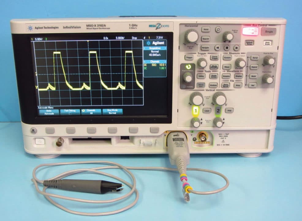
For general-purpose troubleshooting, the minimum recommended model would be a 500 MHz to 1 GHz bandwidth and at least 4GSa/s, or more. Examples might include the Keysight Technologies MSO-X 3000 series (Figure 11). There are many equivalent models from Rhode & Schwarz, Rigol Electronics, Siglent, Tektronix, and Teledyne-LeCroy.
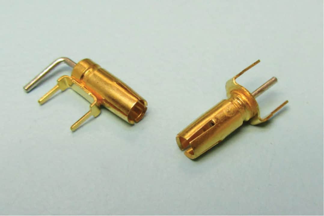
When measuring high-frequency clock signals, be sure the bandwidth of the oscilloscope and probe exceed the measurement you’re making. Minimize the length of the signal return lead of the probe. Using the typical 4 to 6 inch probe ground wire will just accentuate ringing due to the high self-inductance created by the measurement loop area. I advise using the small solder-in probe sockets sold by the top oscilloscope manufacturers (Figure 12). An alternative would be to solder the probe right into the circuitry or to use a 1/4-inch (or shorter) probe ground or signal return connection. An alternative would be to use one of the high frequency active probes, such as the Keysight Technologies model N2976A 2 GHz probe or Rohde & Schwarz 1.5 GHz model RT-ZS20 probe, or equivalent.
Most oscilloscopes today have a fast Fourier transform (FFT) math function that converts time domain signals to the frequency domain. While this could be potentially helpful in troubleshooting, one of the issues is lack of dynamic range and input sensitivity. Most low-cost oscilloscopes can capture only eight bits of data, so very small signals can be buried in the noise floor and may be difficult to observe.
Some of the more expensive models, such as the Rohde & Schwarz RTO or RTE-series have 14-bit acquisition and are sensitive to 1 mV/division. These models are ideal for troubleshooting EMC issues in both the frequency and time domains. Other manufacturers also offer higher analog-to-digital resolution, better sensitivity, and lower noise, and thus are more useful.
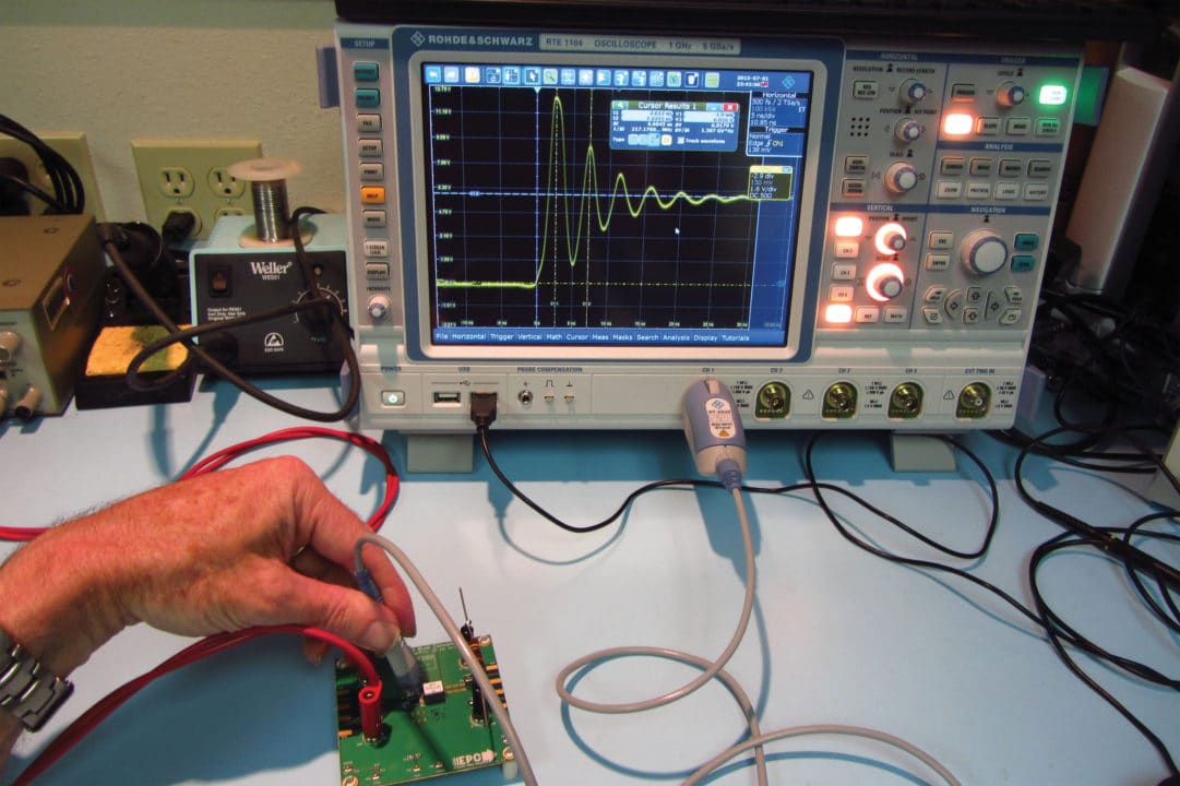
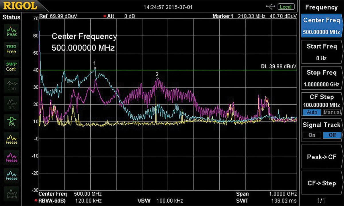
As you can see, the large 217 MHz ringing in the example of Figure 13 has potentially caused large broadband radiated emissions as measured by a current probe on the power supply input and output circuit (marker 1 and 2 in Figure 14).
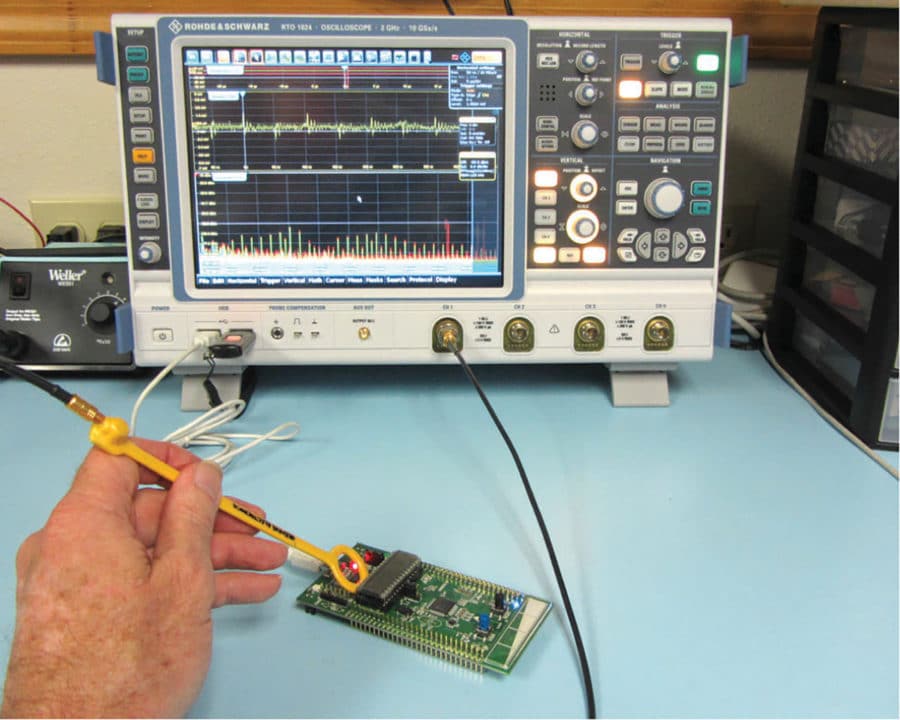
It’s also possible to use near-field probes (H- or E-field) with oscilloscopes. In fact, using one channel as a reference, you can probe with the other to determine correlations between a known noise source and other signals (Figure 15).
MISCELLANEOUS CONTENTS
The following is a list of “small stuff” that you might find very handy (in no particular order).
- Small digital multimeter
- Small driver kit (with an assortment of bits)
- Various hand tools
- Power screwdriver, such as the Ryobi Model HP53L ($30)
- SMA connector wrench
- Pencil soldering iron (Weller WM120, $40)
- Solder and solder-wick
- Dental inspection mirror (small mirror with long thin han-dle for probing in confined spots)
- Small flashlight
- Small magnifier
- ESD wrist strap
- Tape measure (English/metric)
- Tweezers
- X-Actoknife
- Emory cloth (for sanding away paint)
- Wire (miscellaneous sizes and lengths)
- 10 and 20dB attenuators (Mini-Circuits VAT-10W2,VAT-20W2 and HAT-10+, HAT-20+, $12 and $9, respectively, in SMA and/or BNC sizes)
- Various coaxial adapters
- Aluminum foil (1-2 foot square pieces folded)
- Copper tape (or “snail tape”, available from hardware/gar-dening stores at less than $10)
- Insulating Kapton® tape
- EMI gaskets (ask manufacturers for a sample kit)
- Ferrite chokes (chip and leaded beads, clamp-on chokes, ask for a sample kit)
- Capacitors (various values, chip and leaded, in range of val-ues: 100 pF, 1/10/100 nF, 1/10 uF)
- Resistors (various values, chip and leaded in range of values: 1/10/27/47/100/470/1k/10k/100k Ohms)
- Inductors (various values, chip and leaded in range of val-ues: 1/10/100/1000 uH)
- Common-mode chokes (chip and leaded, ask for sample kit)
- External line filter with short line plug (used in-between line cord and product as additional external filtering)
- Small (5×5” bare) copper clad PC board (used for shield – place in a plastic sandwich bag for insulation)
- Clip leads (1m long)
- Various 1m long I/O cables (USB, RS-232,Video VGA, etc.)
- Various BNC and SMA coaxial cables
- Plastic bag with a few coins for generating ESD
- EMI gaskets (ask manufacturers for a sample kit
- Various BNC and SMA coaxial cables
CONCLUSION
This wraps up the description of my EMC troubleshooting kit. As you have probably observed, not all the recommend-ed equipment will fit inside the Pelican transit case. However, if you do need to travel light, most of the important trouble-shooting components will fit, along with the recommended TTi PSA2702T spectrum analyzer or either the Tektronix RSA306 or Signal Hound BB60C real-time analyzers.
REFERENCES
[1] Inexpensive Radiated Immunity Pre-Compliance Testing: https://interferencetechnology.com/inexpensive-radiat-ed-immunity-pre-compliance-testing/
