Editor’s note: This question was asked in response to Interference Technology’s recent webinar by Keith Armstrong. To view the webinar, click here.
Question: Are X2Y capacitors as effective as advertised? Are they easy to design around?
Answer: Well, like Questions 6 and 7 above, this question isn’t related to the subject of my webinar, but I still have some time left to kill on my flight.
X2Y capacitors are very well-balanced internally, using three sets of plates and four sets of terminals, so they have much lower equivalent series inductance (ESL) than ordinary capacitors (two plates, two terminals).
I understand they might even have lower ESL than three-terminal two-plate capacitors, but this is not a very helpful comparison because X2Ys cannot be used as feedthrough capacitors like three-terminal capacitors.
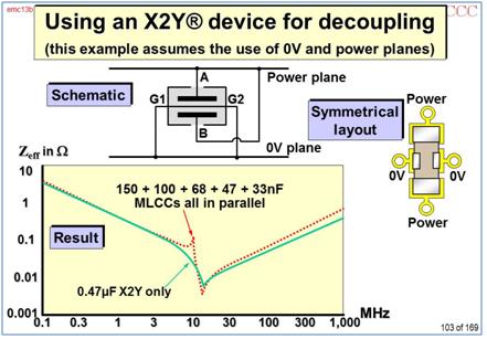
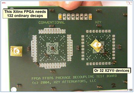
Being very well-balanced, an X2Y can be very much more effective at reducing CM noise or decoupling a PCB power plane, than several ‘ordinary’ components, especially at frequencies above about 300MHz.
Sadly, I’ve not (yet!) had the opportunity to use X2Ys in a project, but the X2Y website (www.x2y.com) has many papers comparing their products with others in real applications using regular EMC measurements, and they seem genuine enough. I’ve had the opportunity to work with X2Y on a few occasions, and they seem to me to be a solid company with an excellent product. I understand that General Motors prefers X2Ys to be used to suppress windscreen wiper motors, where they replace a much larger and more costly assembly and give better suppression.
Because they are not (yet) purchased in high quantities, most X2Ys cost more than the equivalent ordinary capacitors, but because they can replace several ordinary components and save board space, their overall cost is often lower. But if you can use the value(s) of X2Ys that GM’s electronic suppliers purchase, and source them from the same X2Y manufactures – their unit costs should compare quite well with ordinary capacitors of the same size and value!
When designing with them it is very important indeed that they are used in balanced, symmetrical arrangements of conductors (whether PCB traces or wires). They rely on splitting their ‘ground’ current equally between their two G terminals, so if the pad/trace/via hole/plane structure associated with G1 has a different impedance than the pad/trace/via hole/plane structure associated with G2 – the part will not work as well.
What this means in practice, is that the board layout for an X2Y must be symmetrical about an axis through the middle of the device passing through it’s A and B terminals. Rotating the device and its pad patterns about its vertical axis must look no different.
Here are two relevant figures from one of my PCB EMC training courses:
I can’t say what I have found by using X2Ys, because I haven’t used any yet! But as far as I can tell, they really do what they claim to – as long as their design rules are followed correctly. And I’ve never heard or read anywhere, ever, that X2Ys are not as good as their manufacturers claim they are.
-Keith Armstrong


