Tom Mullineaux,
President, Lionheart Southwest. Inc
Introduction
Take a look at any semi-anechoic chamber and they all seem to share the same basic design, that is a long cuboid with six flat faces, five of which are identically clad in RF absorbing materials. However, when utilized for RF immunity testing, the performance of the chamber is pretty much dictated by the performance of one wall. That wall is the absorber clad wall that faces the antenna. This article argues that well known stealth techniques could be incorporated in the design of this ‘hot’ wall so that the chamber exhibits superior all round performance.
Background
Achieving field uniformity in a 3 meter semi-anechoic chamber has always been troublesome, and made more so with the need to test up to 6GHz. After much experimentation, test-houses discovered the pragmatic solution was to point the antenna into a corner of the chamber. A moment’s thought tells you that the key difference compared to firing the RF straight at the flat face of the hot wall is that some or all of the RF wave is diverted (by reflection) away from the calibration plane.
This can be hard to visualize, so to help gain a rudimentary understanding of the chamber dynamics under these corner illumination conditions, we will apply simple ray tracing. For another method see Note 1.
With ray tracing it is assumed an emitted wave can be modeled as a large number of rays. For our purposes a large number would cause visual overcrowding, so for clarity we will use only three cardinal rays: the bore-sight ray, and the two half-power rays that define the antenna beamwidth limits.
Figure 1 shows the basic idea
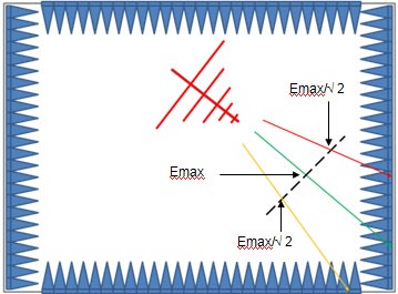
The figure shows a plan view of a chamber (not to scale). The antenna (Note 2) is shown illuminating the calibration plane (black dashed line) and the corner of the chamber.
The maximum field strength Emax occurs along the boresight ray (green). The field will be at Emax /√2 along the rays defining the half-power beamwidth (red and orange).
The test frequency is high so only the shorter rods of the antenna are active and the beamwidth is comparatively narrow
Figure 2 shows the three resultant reflected rays.
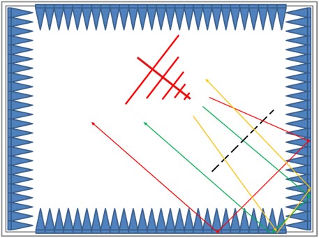
It can be seen that the green boresight ray and the red half-power ray pass through the calibration plane once only (the ideal), but unfortunately the orange ray passes through twice. However, this is better than all three re-passing through the plane as is the case with the antenna facing the hot wall. On route, the orange ray passes through two attenuation interfaces, which although the ray is not impinging at the intended normal incidence, could result in greater attenuation than a single pass at normal incidence. The intention is to determine the level of attenuation of this non-normal incidence route using 3D EM software, see Note 1.
Given that this pragmatic approach uses deflection to help achieve a uniform field, and that this is a key principle used by stealth aircraft, is it feasible to apply stealth principles to the hot wall?
To examine this prospect, we first need to introduce a key concept used in stealth technology – RADAR Cross Section (RCS).
RADAR Cross Section
A simplistic way of looking at the RADAR Cross Section (RCS) concept is to consider a target comprised of a 1 meter square, fully reflecting sheet, facing the RADAR system antenna. We then fire a RADAR pulse at the sheet resulting in an echo that is detected and processed by the RADAR system. The strength of the echo return from this ideal reflector is now used as the base-line comparator. Echoes from aircraft are then compared to this ideal echo signal strength. Particular aircraft can then be allotted a RCS number (in meters squared). Stealth technology strives to obtain the lowest RCS possible.
Figure 3(a) shows the 1 meter squared sheet from the side (the point of view of the RADAR antenna) and from above. The green arrows represent the incident RF, the red ones the echo heading back to the RADAR antenna.
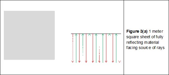
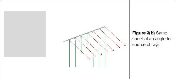
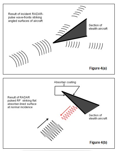
Figure 3(b) shows the sheet turned at an angle to the source of RF. The RCS plummets due to the deflection of the RF echo away from the antenna. Although about 90% of the sheet area is still visible to our eyes, the sheet is almost invisible to the RADAR system due to the weakness of the echo returned in the direction of the receive antenna. The stealth aircraft implementation is shown in Figure 4(a)
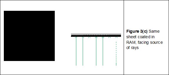
A second key principle used by Stealth to reduce RCS is attenuation of the returned echo through RADAR absorptive coating. This is what the chamber cladding strives for too, of course. The ideal (100% absorption) is shown in Figure 3(c) and the stealth aircraft implementation is shown in Figure 4(b)
Applying these Stealth Principles to the Hot Wall
In terms of this application, applying stealth techniques means the field emanating from the antenna makes a single pass through the calibration plane from a single direction. So the minimized RCS is from the perspective of the calibration plane. That is the new hot wall should be all but invisible to a field probe located anywhere on the calibration plane.
Clearly the new hot wall design will strive to use deflection and attenuation to achieve this.
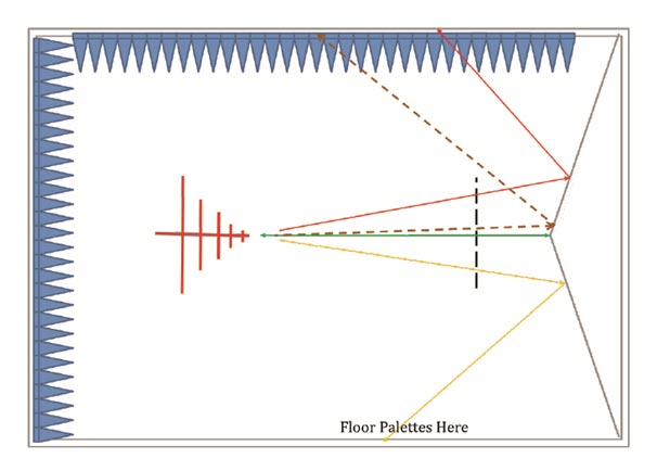
Figure 5 shows one possible arrangement. The hot wall is comprised of a flat sided fully reflective 3D pyramid with it’s apex centered on the antenna boresight. For clarity the cladding has been omitted from the hot wall along with the temporary 1 meter wide cladding ‘palettes’ that are placed on the floor between the calibration plane and the antenna mount (see below).
Taking the three cardinal rays one at a time:-
• The top one (red) is nicely deflected
• The bottom one (orange) is deflected down to the floor mounted attenuator palettes, or if it lands to one side of a palette, it is further deflected away from the calibration plane
• The boresight ray is an issue as it will be reflected straight back at the antenna, passing through the calibration plane again as it goes
To put the amount of reflected field from the boresight ray in perspective, it should be remembered that the surface area of the apex point facing the antenna will be tiny, and as shown by a neighboring ray with a small angular offset ( Figure 5, brown dashed-line), rays with even a slight offset angle do not revisit the calibration plane.
As regards lower frequency attenuation, the ferrite tiles would have to be cut or formed to the shape of the apex faces, and also to fit along the edges where the pyramid faces meet. This will increase the effective area facing the antenna, but the total area will still be tiny compared to illuminating a flat wall at normal incidence.
Cladding the Pyramid
For the proposed new hot wall design, non-standard- cut / formed pyramidal absorber matrices would be required so they face squarely towards the opposite wall. Also, as previously mentioned, ferrite tiles may need to be pre-molded to cater for the angled faces and the apex of the new wall.
Cladding the Floor
This practice is already commonplace due to the difficulty of achieving field uniformity. The palettes are arranged to form a continuous line one meter wide line between the antenna and the calibration plane.
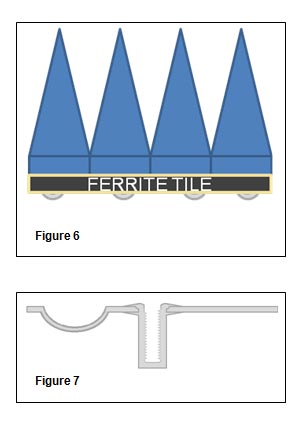
A cross section of a typical palette with its castors is shown in Figure 6. These are rolled into place during the test set-up. For repeatability, there should be clamping mechanisms that ensure the palettes are aligned consistently. Figure 7 shows one way to do this, where all the castors sit in their respective recess in the floor and the palette is then lined up and fastened in place (four anchor points total).
Conclusion
On the face of it, it should be perfectly feasible to obtain field uniformity with the antenna facing a flat absorber clad wall. Plainly this is not the case as evidenced by the need to point the antenna into a corner. If this pragmatic solution is in fact employing stealth techniques, then why not go the whole hog and employ them intentionally? The key to field uniformity is for the RF wave to make a single pass through the calibration plane from a single direction. Using stealth principles epitomized by stealth aircraft is a giant step towards achieving this. Obstacles to this or a similar solution being adopted include the added complexity (read expense) of manufacture and assembly. However, 3 meter semi-anechoic chambers are artificially high due to the scan height requirement used at OATS (Open Area Test Site) facilities. If it turns out the new hot wall results in a vastly superior quiet zone, maybe one day the additional height will be unnecessary and would be a good trade for the extra length required for the new hot wall.
Notes:
1. The intention is that a 3D EM analysis of a contoured hot face will be published on Interference Technology’s website blog page (EMC-Zone). Thanks are owed to CST for the kind loan of their CST Studio Suite ® 2014
2. For ease of visualization the antenna is shown horizontally polarized. In the 3D EM analysis the antenna will be vertically and horizontally polarized


