Losses can arise from polarization mismatches.
Ricardo Perez
Alion Science and Technology, Annapolis, MD
Antenna polarization is one of many parameters to consider when designing a system. The polarization of the transmitter antenna in a system should be properly aligned with the receiver antenna to maximize coupling. Maximum signal coupling between stations occurs when both antennas are using the same polarization.
In a linearly polarized system, a polarization misalignment of 45 degrees will degrade the signal up to 3 dB. Polarization misalignment near 90 degrees can result in signal degradation greater than 20 dB. Accurate measurements of signal strength at polarization near 0 degrees and from 80 degrees to 90 degrees require careful control of the positioner and signal strength meter.

This article describes the procedures used for a recent antenna polarization-mismatch measurement project and includes an equipment diagram, equipment list, and summary of the results.
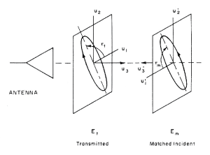
When an antenna receives a field from a particular direction, the captured signal will be greatest if the polarization of the incident wave has the same spatial orientation as the antenna. A diagram of a matched field orientation is shown in Figure 1, where E t represents a specific transmitted polarized E-field generated by the transmitting antenna, and Em represents the matched incident field. Although the sense of polarization for Et and Em are the same, the angles are offset by 180 degrees because the coordinate system at Em (u’1, u’2, u’3 ) is rotated 180 degrees about the vertical axis relative to that of Et (u1, u2, u3 ). The angle tt is the tilt angle of the transmitted field, and the angle tm is the tilt angle of the matched received field. These angles are related by the following equation:
tm=180 – tt
When the polarization alignment of a receive antenna is different from the incident field polarization, a loss due to polarization mismatch occurs. For the case of linear polarization, the relative power level of the signal captured from the field at Em is theoretically described by the following equation:
relative power level, Em = 20*log(cos ( t m ))
MEASUREMENT EQUIPMENT

Measurements were performed using a highly stable signal generator (SG), in this case an Agilent E4437B. This SG was used because measuring accurate changes in received power levels proved to be taxing for the largest and smallest mismatch angles. An HP8112A pulse generator (PG) was used to drive a servomotor that controlled the antenna tilt or polarization angle. A rotating dipole assembly GFR-1 Feed (L-band) was used as the receiving antenna and an SAS-200/510 log periodic antenna was used as the transmitting antenna. An HP8563 Spectrum Analyzer (SA) was used to measure the power level received through the dipole antenna.
MEASUREMENT SETUP

In general, the rotating dipole antenna may be configured as either a receiver or transmitter. For these measurements the dipole was configured as a receiver, as shown in Figure 2. The receive antenna was connected to the spectrum analyzer input connector.
A 5-volt direct current motor controlled the dipole polarization angle. A constant 5-volt level at the motor causes the dipole to continuously rotate, whereas a zero volt level will stop the dipole at its last position. A protractor, marked with steps of 1 degree from 0 to 359, was placed behind the rotating dipole for angle measurements.
A 5-volt direct current motor controlled the dipole polarization angle. A constant 5-volt level at the motor causes the dipole to continuously rotate, whereas a zero volt level will stop the dipole at its last position. A protractor, marked with steps of 1 degree from 0 to 359, was placed behind the rotating dipole for angle measurements.

CONCLUSION
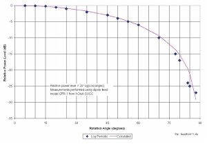
Power level losses as a function of polarization mismatch angle are shown in Table 1 and plotted in Figure 3. Measured values agreed with calculated values very closely up to 60 degrees. Measurement results for mismatch angles greater than 88 degrees varied by more than 2 dB, so the values were not recorded.
ACKNOWLEDGEMENT
Many thanks to Lloyd Apirian and Mike Dion for their comments and technical review.
REFERENCES
- Antenna Engineering Handbook Second Edition, McGraw-Hill Book Company Richard C. Johnson and Henry Jasik
- IEEE Standard Test Procedures for Antennas, IEEE Std. 149-1979, Institute of Electrical and Electronic Engineers, New York, 1979, sec. 11.
