Pascal De Resseguier, Entares Engineering, Toulouse, France
Yannick Poiré and Samuel Leman, Nexio, Toulouse, France
ABSTRACT
A proper study of electromagnetic interferences inside an aircraft has become essential with the recent increase of electronic devices on board. Their effects on the airplane communication and electronic systems need to be considered at an early stage of the design process. Numerical simulations are often used to perform this analysis. However, the large electrical size of the model at high frequencies provokes significant computational time and memory requirements. Although a number of “fast” iterative methods exist, the cavity-like structure of the aircraft arises some convergence issues reducing their applicability for this sort of problem. The proposed direct method solves the Method of Moments (MoM) linear system by the use of the Adaptive Cross Approximation (ACA) algorithm to reduce the matrix size and computational time. Unlike “fast” iterative solvers, a direct approach is used to avoid convergence problems. A good agreement between simulations with CAPITOLE-EM software using ACA compression and measurements is shown for a simplified aircraft mockup.
INTRODUCTION
The number of passengers boarding airplanes with PED (Personal Electronic Devices) has grown significantly in the last decade. Uses of PED are generally forbidden during critical stages of a flight due to their power to interfere with the airplane systems. Nonetheless, it is important to study EMI (electromagnetic interference) early in the design phase to minimize the possible effects.
An airplane fuselage can be assimilated to a cylindrical metallic cavity with apertures for windows. When it is excited by an antenna, resonances on electric and magnetic fields appear at some frequencies which might create interferences with some airplane equipment, with the obvious implications in security issues it could represent.
To analyze these coupling effects, various methods have been used until now, such as the Finite Difference Time Domain (FDTD) [1] and the Method of Moments (MoM) [2] among others. However, the devices operating frequency along with size of airplane is increasing, calling for prohibitive computational time and memory requirement.
Several so-called « Fast methods » such as AIM [3], MLFMA [4], MLMDA [5], and ACA [6] have been developed to efficiently solve electrical large objects provided by the MoM. All these methods are based on an approximation of the impedance matrix in a compressed form, hence reducing its size. Generally, the system is solved by an iterative algorithm, involving a matrix-vector product per iteration. Thanks to the compression of the impedance matrix, the computational cost of the solution process is highly reduced.
Although these methods, and in particular the MLFMA, are very efficient for electrical large problems, there are certain cases where iterative methods show slow convergence or even fail to converge. In general, it is difficult to predict the convergence of a given problem, but cavity structures are commonly hard to solve. The method presented here is based on the MoM-EFIE, with a significant reduction of computational time while avoiding any convergence problem.
In Section II, the compression of the impedance matrix with the use of the ACA algorithm is briefly explained. Section III describes the factorization for the direct inversion process. Finally, Section IV exposes a comparison between the classical MoM and the « Fast » iterative method, together with a validation of measurements on a mockup.

ACA COMPRESSION ALGORITHM
The described method is based on the compression of the MoM impedance matrix by blocks. The key point is that the matrix blocks representing the interaction between two geometrically separated groups of elements are rank-deficient.
A binary tree algorithm is used to subdivide the impedance matrix into blocks (Figure 1). The elements are successively split following their space distribution into two groups until a given number of elements per group is reached.
Diagonal blocks, which correspond to self-group interactions, are computed with the classical MoM method while off-diagonal blocks, which represent the interaction between two well-separated blocks, are computed with the ACA Algorithm.
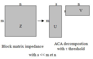
The ACA was introduced by Bebendorf [7] to compute a compressed form of low rank matrices using only a few elements of the original matrix. Therefore, each matrix block can be approximated by a product of two matrices of smaller size:
![]() being M a m×n matrix, U a m×k matrix and V a k×n matrix with k<<m,n, where k is the τ-rank of the matrix block (Figure 2). The error is controlled by a threshold τ which determines when to stop looking for more columns and rows of U and V, respectively. This results in a reduction of memory storage as well as computational time. This algorithm is purely algebraic, so it does not depend on the integral equation kernel and therefore can be easily integrated into an existing MoM code.
being M a m×n matrix, U a m×k matrix and V a k×n matrix with k<<m,n, where k is the τ-rank of the matrix block (Figure 2). The error is controlled by a threshold τ which determines when to stop looking for more columns and rows of U and V, respectively. This results in a reduction of memory storage as well as computational time. This algorithm is purely algebraic, so it does not depend on the integral equation kernel and therefore can be easily integrated into an existing MoM code.
A SVD re-compression is done on the matrix generated by the ACA algorithm to obtain a further compression and to have the matrix on SVD form for the solving process. A SVD threshold ten times higher than the ACA one is chosen.
BLOCK LU DECOMPOSITION
Once the compressed matrix is computed, a direct block-wise method is used. Although generally slower for the solution of one incidence vector than accelerated iterative methods, the direct method avoids convergence problems as it reaches a solution in a predictive time. Not forgetting the negligible extra time if the solution for several input vectors is required, which is usually the case in most applications.
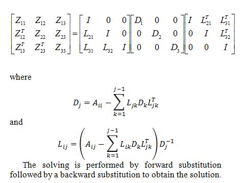
In particular, we use a block LDLt factorization for symmetric indefinite matrices, where L is lower triangular, D diagonal blocks and T represents the transpose. This is a generalization of the Cholesky factorization, which requires positive semi-definiteness. A representation of this decomposition when the matrix is subdivided in 3×3 blocks is shown below:
In order to validate the solving method using the compression algorithm ACA we conducted three types of comparisons: with the reference uncompressed MoM method, with the fast method MLFMA and finally with measurements on a simplified scaled airplane model.

Presentation of the Model
The model used for the validation represents an airplane inspired on the CASA CN-235 from EADS. Simple shapes have been chosen to facilitate the manufacture of the physical model. However, volumes have been respected at a fixed scale factor (Figure 3).

The fuselage is simplified by a cylinder with a length of 150 cm and a diameter of 47 cm. A plane floor is placed 29 cm from the top of the cylinder. A series of small apertures on both side of the cylinder have been drilled for the windows. The cockpit is represented by a truncated cone 27.3 cm long, adjusted to the cylinder at its largest section and with a diameter of 24 cm at its smallest. Apertures for windows have also been drilled in the cockpit. A floor has also been placed in the cockpit at the same height than in the cabin. Note that there is a small gap between the floor and the external part which are supported by two longitudinal PVC wedges.
Several 2 cm monopoles are placed at different locations inside the structure to model the antennas. Cables are represented by rectilinear wire conductors connected to the board.
The model has been built in aluminum with a thickness of 2 mm (Figure 4).
Numerical Validation
The following simulations have been performed on a DELL PRECISION 690 workstation with a quadcore Intel Xeon E5345 processor at 2.33GHz and 12GB memory. CAPITOLE-EM software from Entares Engineering has been used for numerical simulations using parallellism.
For the first case, a comparison between the compressed method ACA and the conventional MoM is made. For this case, the model was simply the cylinder with two monopoles inside.
The matrix size was reduced by 84.8% while the CPU time was almost ten times lower (see Table 1).

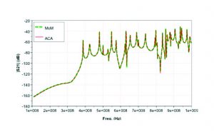
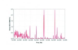
The result of the coupling between the two monopoles is shown in Figure 5. An excellent agreement is observed. Figure 6 shows the percentage error between the two curves, mostly below 1% and seldom 2.4% which represents a difference of 0.5dB for a dynamic range larger than 100dB.
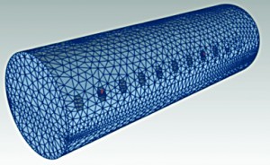
For the second test, the cylinder model with windows and a floor has been used. A comparison with the MLFMA method has been performed.
Table 2 summarizes the performances of the two methods. Even though the MLFMA has a better compression, the computational time is much higher. This is due to the convergence of the iterative solver, especially for frequencies above 700MHz (see Figure 9).
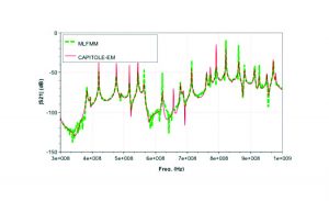
Note that even in the cases where MLFMA reaches the maximum number of iterations without convergence, the obtained coupling value is very close to the actual one, meaning that the algorithm has practically converged.
Validation by Measurements

Measurements have been performed on the complete aluminum model.
The S21 parameter between an interference source and a receiver has been measured with a vector analyzer VNA.
The first case is a coupling between two monopoles over the floor of the cabin. Figure 10 presents the results of the simulation and the measurements. It resembles the shape of a direct coupling between two near monopoles superposed to the resonances of the cavity.

A good agreement between measurements and simulation can be observed. It properly recovers the average level and the resonances.

The second case measures the coupling between a monopole placed inside the cockpit and a cable running through the wall and extending into the cabin. Figure 11 shows a good correlation apart from the frequency range around 510MHz.
The length of the intersection between the cockpit floor and the piece of cone is about 29.5cm and it is provided with slots on both sides. If you look at the resonance frequency at λ / 2, we obtain 3e8/29.5e-2/2 = 508MHz, resonance appearing in the simulation. It is reasonable to assume that this resonance is missing in the measurements because of the PVC wedges used to support the floor.
CONCLUSION
In this document, a solving method based on the ACA algorithm for compression of matrices derived from the method of moments has been described and applied to the study of couplings in a resonant cavity. A comparison with the conventional MoM method has shown the good precision of this method. We have observed how the MLFMA has some convergence difficulties for this particular case. And finally, a good agreement with measurements has been observed.
In recent years the so-called “fast” methods have revolutionized dramatically electromagnetic simulation, reducing computational time and memory space. Notwithstanding, the presented method, although less efficient on very electrically-large models, can be interesting for intermediate size models with larger complexity such as cavities.
REFERENCES
[1] K. S. Yee, “Numerical solution of initial boundary value problems involving Maxwell’s equations in isotropic media,” IEEE Trans. Antennas Propagat., vol. AP-14, pp. 302–307, May 1966
[2] R. F. Harrington, Field Computation by Moment Methods, MacMillan, New York, 1968
[3] E. Bleszynski, M. Bleszynski and T. Jaroszewicz, Adaptive Integral Method for Solving Large-scale Electromagnetic scattering and Radiation Problems, Radio Science, vol.31, no.5, pp1225-1251, 1996, Sep.-Oct.
[4] J. Song, C.C. Lu and W.C. Chew, Multilevel Fast Multipole Algorithm for Electromagnetic Scattering by Large Complex Objects, IEEE Trans. On Antennas and Propag., Vol. 45, No. 10, pp. 1488-1493, October 1997.
[5] E. Michielsen and A. Boag, A multilevel matrix decomposition algorithm for analyzing scattering from large structures, IEEE Trans. on Antennas and Propag., Vol. 44, No. 8. 1086-1093, Aug. 1996.
[6] K. Zhao, M. Vouvakis, and J.-F. Lee, “The adaptive cross approximation algorithm for accelerated method of moment computations of EMC problems”, IEEE Trans. on Electromagnetic Compatibility, vol. 47, no. 4, pp. 763–773, Nov. 2005.
[7] M. Bebendorf “Approximation of boundary element matrices”, Numer. Math., vol. 86, pp.565 – 589, 2000

