The many devices used in an industrial setting can present significant challenges in emissions control.
Vinod Kumar Dhar
Electronics Regional Test Laboratory (West), Indian Ministry of Information Technology, Mumbai, India
While controlling electromagnetic interference is a worldwide challenge encountered in homes, shops, and offices, that task can be particularly difficult on the factory floor. Before tackling such a challenge, a basic review of EMI phenomena is in order. Essentially, the designer must deal with unintended electromagnetic energy found in power or signal lines or radiated through free space. Whether it occurs within one system or affects nearby machinery, EMI has the potential for causing malfunctions and equipment failure. An additional challenge involves the interconnection of devices, each of which may carry the CE mark. To their dismay, factory operators have learned that the faulty configuration of devices can be just as disastrous as opting for components lacking the CE stamp. A final challenge involves the unavoidable connection of the machinery to high power utility mains—another potential source of “electrical pollution” that can affect all the equipment within a plant.
Ultimately, detecting and controlling EMI requires an understanding of the source, the propagation path, and the effects on the “victimized” equipment. The simplest coupling path is usually copper wire in the form of power cables connecting the equipment to the electric utility. Power line disturbances can occur in either common or differential mode. In common mode, EMI voltages will appear between the current-carrying conductors (line and neutral) and ground, and they will be in phase. In differential mode, the EMI voltage will appear between the individual conductors and will be out of phase.
THE DUT
In this particular instance, the machinery being evaluated was a pillar bin-blending machine, the device that mixes powdered or granular pharmaceutical ingredients. This blending device includes an AC frequency drive, contactors, relays, control circuitry, timers, proximity sensors, and motors. The high frequency drives used in this kind of industrial machinery can be a significant source of interference, and its severity is determined by such factors as the frequency of operation, the type of control circuitry, and the choice of contactors, timers, and motors. Additionally, not all of the unwanted energy traveling along signal or power lines results from a galvanic attachment. Capacitive and inductive couplings also spread these AC signals.
Specifically, this machine is a dry mixer of powders and granules. It requires no packing seals around the shafts entering the chamber. This device is chosen for blending operations because it is easy to load and unload, handles a large capacity, and results in minimal attrition of the pharmaceutical product while blending fragile granules. Mixing is achieved in a closed drum. Thorough admixture is the goal. If the finer particles of the mixture become airborne, they will settle on top of the powder bed within the drum once the blending action has stopped, thus creating an unincorporated top layer. The process is as follows. Pharmaceutical granules or powders are added to fill the drum to 50–70 percent of capacity. The loaded bin is then locked onto an arm of the device and raised upward on a column. Once the bin is raised to the correct height, the operator presets the blending time and speed. Greater speed produces increased shear, which in turn produces undesirable airborne particles. Optimal blending for a substance is achieved by adjusting the speed. Once the particles are blended, the drum is lowered, the arm is unlocked, and the closed bin removed.

DETAILS OF ELECTRICAL BLOCKS

In terms of EMC compliance, the tester must turn his attention to the two motors involved and their power source and controls. A gear motor with a lead screw is mounted atop the column and a blending motor creates the tumbling within the closed drum. (The exact configuration of a pillar bin-blending machine is shown in Figure 1.) Figure 2 depicts the electrical blocks of the system—i.e., the mains panel, control panel, and motor panel. Input voltage of 440 VAC/50 Hz is supplied via an unshielded power mains cable 1.5 m in length. This cable connects to the power line filter, and the output of the filter connects to the mains isolator switch. The voltage from the mains isolator is then fed to a contactor via miniature circuit breaker (MCB). Through the contactor, voltage passes to another filter, which in turn channels voltage to the input of the AC frequency drive. The output of the frequency drive connects to the input of the motors mounted on the pillar blender.
From the same mains, power flows to the blender brakes and control circuitry. The power passes through a contactor to the blender brakes that operate at 240 VAC/50 Hz. R-phase and B-phase (440 VAC/50 Hz) flow in parallel through an MCB and step-down transformer to provide 240 VAC/50 Hz to the input of the control circuitry. (See Figure 2.) The control circuitry operates the blender timer crucial to the efficient blending of the granules or powder.
MODELING AND TEST SET-UPS
An initial examination of machine and the arrangement of mains power and the control power indicated the possibility of EMI problems. Careful study of the machine revealed haphazard wiring and the presence of many loops—although the machine did perform its basic function of blending powders. The presence of two filters did little to alleviate problems since input and output cables for both power and driver were scrambled together haphazardly, running in parallel or in obvious loops. In fact, simply locating the power lines was a daunting task. Eventually, the tester tackled the problems with three models: one for the AC frequency drive, one for control panel routing, and one for selection of appropriate filtering and grounding. Of course, complete analysis and resolution of the problems require measurement and evaluation of conducted EMI levels and common mode noise voltage.
International standards intended to control or limit interference with radio or television transmission call for testing with EMI receivers or transducers responsive to this particular type of noise. In this case, the receiver and accessories met specifications set forth in CISPR-16-1. The EMI receiver is used to study/analyze the energy distribution across the frequency spectrum of an electronic signal, while the line impedance stabilization network (LISN) is used primarily to provide a defined impedance at high frequencies across the power feed of the terminal voltage at the points of measurement. It also provides insulation from the ambient radio-frequency energy on the power lines to the equipment under test (EUT).


The conducted emission (CE) test set-up (as recommended in CISPR specifications) is shown in Figure 6. In this set-up, a ground reference plane (GRP) of 2m by 2m is required. The LISN is kept at a specified distance, and its ground terminal is bonded to the GRP by the shortest possible connection, as shown in Figure 6. This test set-up is automated to facilitate fast measurements over a wide range of frequencies. The application software automatically measures peak emissions levels on the EMI receiver at preset frequencies, and the results are shown on VDUs (visual display units) or on the EMI receiver. Data “dumped” on the unit plot the observed emissions levels, and hard copies of data can be printed out.
Comprehensive EMI analysis involves three modes, or types, of emission detection—viz., peak, average, and quasi-peak. In peak detection, the envelope of a signal is measured and displayed along with the measured value of the RMS (root mean square) signal to the CW (continuous wave) signal. If no modulation exists on the signal, then the peak voltage has been detected. Peak voltage detection assures that the “worst case scenario” for emission data has been obtained.
For average voltage detection, basic circuitry involves an envelope detector (comparable to the peak detector) followed by an averaging network. This circuit is simply a low-pass or integrator/capacitor. An additional smoothing network includes a series of resistance and shunt capacitors—producing an end-result of an averaging of random noise. This particular mode of detection is often used for analyzing narrowband emission signals. Finally, in quasi-peak detection, broadband signals are analyzed by incorporating various charge and discharge constants (depending on the frequency range) as a function of pulse repetition rate. Essentially, it is used to evaluate the “annoyance” factor.
EMI ANALYSIS

In EMI analysis, signals are classified as either broadband or narrowband emission signals. The term broadband denotes a signal in which the is greater than the reference bandwidth and the pulse repetition frequency (PRF) is less than the reference bandwidth. In contrast, the narrowband signal is characterized by a bandwidth less than the reference signal, and a PRF greater than the reference bandwidth. Before analyzing the actual measurement data obtained from the pillar blending machine, a review of the regulatory limits of BS EN 50081-2[4] is in order.

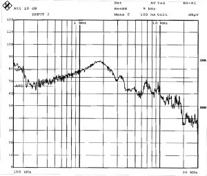
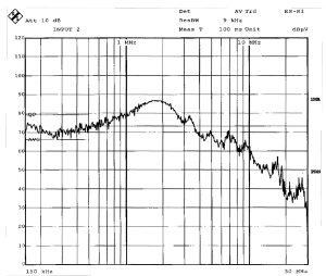
Initially, the EUT configured as per the manufacturer’s design and shown in Figure 2 was tested at full speed operation at rated load conditions. The test data obtained in R, Y, and B phases and in the neutral configuration of the EUT are shown in Plots 1, 2, 3, and 4, respectively. The data show that observed peak omissions have exceeded average regulatory limits in the ranges of 150 to 500 kHz and 2.4 to 10 MHz while leveling off around 86 to 60 dBμV maximum. The peak emissions have also exceeded quasi-peak regulatory limits regulatory limits in the frequency range of 500 kHz to 3.4 MHz and then level off at about 86 to 63 dBμV over the desired frequency range. Excluding some spot frequencies, these observations held true for emission levels in individual phases and in neutral configuration.

Clearly, the pillar bin-blending machine failed to comply with the applicable international standards. Basic principles for achieving EMC had been ignored in the design of this device—a sorry state of affairs clearly reflected in inadequate filtering and shielding, the absence of grounding integrity, and the lack of noise mitigation. Above all, the basic physical design of the AC drive contributed to compliance failure.

DESIGN REMEDIATION
A first step in controlling or reducing the emission levels produced by the EUT involved altering the physical layout of the AC design drive as shown in Figure 4.
Specifically, the unshielded cables connecting the motors were replaced by shielded ones. The shield termination at the side of the drive was connected to ground, while another shield termination at the motor load side was connected to the motor chassis. Segregation of the input and output cables of the AC drive was achieved by routing them through separate channels in the panel. Grounding integrity was improved by choosing an adequate wire gauge and the shortest feasible connection to the chassis. Finally, a filter circuit was incorporated in the housing of the EUT, and its power cord was restricted to less than one meter.
Filter components selected had nominal values as given:
Inductance (L) = 2.4 mH/line
X-capacitor = 0.3 μF
Y-capacitor = 0.041 nF
The newly designed filter has an operating voltage of voltage of 440 VAC/50 Hz and can sustain a load current of 15 amperes maximum.
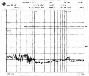
The EUT was then re-evaluated with the redesigned layout as shown in Figure 3. It was tested at full speed operation at rated load conditions with all remedial measures in place. The test data for emission levels in R, Y, and B phases and in neutral are shown in Plots 5, 6, 7, and 8, respectively. The new data show that the emission peak levels are well below both average and peak quasi-peak regulatory limits over the desired frequency spectrum. At some points along the subject frequency range, the observed emission peaks level off at about 30 to 34 dBμV. Clearly, careful design combined with adequate filtering, shielding, and grounding are vital steps in designing industrial machine that comply with international standards and qualify for the CE mark.
CONCLUSION
Industrial machinery inevitably involves complex circuitry. Necessary industrial processes involve the integration of various components along with the panels that allow for operator control. As the testing of the pillar bin-blending machines demonstrated, such machinery may carry out its basic function while falling short of relevant EMC standards. It should be noted that achieving EMC requires a comprehensive approach. Piecemeal solutions are inadequate. Every design factor that affects emissions must be addressed. These factors include adequate shielding, grounding, and filtering, as well as shortened cabling to forestall unwanted coupling. In addition to overcoming unacceptable emissions, changes in the electronics of the bin-blender made it less susceptible to interference from other devices in the pharmaceutical plant, and the CE mark could be affixed to these device with confidence.


ACKNOWLEDGEMENTS
The author expresses his sincere thanks to Shri P.H. Bhave, Senior Director, ERTL (W), for his guidance and inspiration in the preparation of technical writings on EMC. Also, sincere thanks to my wife, Mrs. Asha Fetedar, for her help and unstinting encouragement.
REFERENCES
1. P.S. Bimbhre. Generalized Theory of Electrical Machines Handbook. July, 1985, pp 448 to 469.
2. Violette, J.L. Norman, Electromagnetic Compatibility Handbook. November, 1987, pp 453 to 469.
3. Rohde and Schwarz, “Operational Manual of R&S ESI 26 EMI Receiver,” March 2001, pp E-1 to E-14.
4. BS EN 55104-1, Electromagnetic Compatibility Requirements for Industrial Environment, July 1995, pp 1 to 7.
ABOUT THE AUTHOR
Vindo Kumar Dhar is an EMC Scientist who has worked in the Ministry of Information Technology for the past 15 years at ERTL (W), Mumbai, India. His responsibilities include EMC laboratory setup, equipment installation, evaluation of products as per international standards, calibration of EMC equipment, and upgrade of test facilities. He also consults on EMC issues involving domestic, commercial, industrial, scientific, medical, and automotive electronic products. He has authored more than 25 pragmatic studies on EMC topics.


