Have the new standards improved measurement accuracy?
Ken Hall
Hewlett Packard, Roseville, CA, USA
This article presents the results of an inter-laboratory comparison of a flicker measurement system. In the process of evaluating replacement equipment that met the new international requirements of IEC 61000-3-2,1 harmonics, and IEC 61000-3-3,2 voltage fluctuations commonly called flicker, we tested several demonstration harmonic and flickermeters using a laser printer. Depending on the flickermeter, the Pst (short term flicker) varied both above and below the IEC 61000-3-3(1) limit which prompted the round robin of testing. For credibility, we purchased a calibrated York EMC HFG01(2) (Harmonics Flicker Generator). The flickermeters evaluated were designed to meet the requirements of IEC 61000-3-3 and IEC 61000-4-15.
INTRODUCTION
In the process of evaluating replacement equipment that meets the new requirements of IEC 61000-3-2 and IEC61000-3-3, we put together a round robin that evaluated multiple vendors’ equipment using the York EMC HFG01 and a laser printer. Round robin participants were HP Roseville, CA; HP, Cupertino, CA; TÜV Rhineland, Pleasanton, CA; UL, Santa Clara, CA; Intertek, Menlo Park, CA; Philips Medical Systems, Andover, MA; LEM NORMA, Brunn am Gebirge, Austria; and Austrian Research Center, Seibersdorf, Austria. This paper reports on measurements made by seventeen flickermeters. Seven were at other laboratories, the remaining were HP Roseville units or demonstration units evaluated at HP Roseville. Two of the vendors’ flickermeters were used twice in the evaluations; their measurements were similar.

OVERVIEW

Flickermeters from twelve vendors were used in the evaluations. Ten claim they meet the new requirement of IEC 61000-3-3 + A1 and IEC 61000-4-153; the other two do not. There are significant technical changes (involving zero-crossings) between the older and the revised standards. These changes had been intended to improve accuracy, repeatability and reproducibility of flickermeters. We found that they did not do so. After this round robin, information was presented to the standards working group IEC 77A/WG-2 and CENELEC TC-210; two articles were published—one by Mathieu van den Bergh4 and the other by Mathieu van den Bergh and John Woodgate5 explaining how to improve/verify flickermeter accuracy. This information should be in the standards.
EQUIPMENT
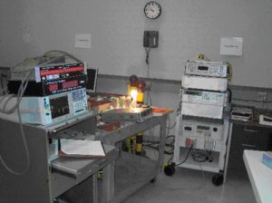
The flickermeters used were Hewlett Packard/Aligent 6843A; EM Test – DPA500; Voltech – PM3000A; Voltech – PM3000ACE; California Instruments– PACS-1; Schaffner – ProfLine 2105; Zimmer – LMG95; Valhalla – D6100; HV Technologies – HAR-1000P; Power Measurement – ION 7600; Xitron – 2503A; Spitzenberger + Spies GmbH & Co. KG – PAS5000; and LEM NORMA 4000. Figure 1 shows the test area and several of the flickermeters. Figure 2 is a photograph of the York HFG01.
RESULTS
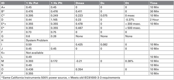
The HFG01 was designed by York EMC Services Ltd. for the purpose of verifying harmonic and flicker test equipment. In the flicker mode, a fixed level of mains disturbance is generated at a rate of 8.33 Hz or 1 Hz. When tested to EN/IEC 61000-3-3, the 8.33-Hz rate produces a Pst >1, which falls above the limit line. The 1-Hz setting produces a Pst <1, which falls below the same limit. Table 1 displays the data obtained from the flickermeters when the HFG01 was set to 8.33 Hz. One of the flickermeter systems, ID “H”, reported a Pst of 2.9, which is almost three times higher than expected and was removed from the remaining tests. For the most part, we measured the HFG01 for one 10-minute flicker measurement cycle. The IEC 61000-3-3 limit for Pst is 0.65 and Plt is 1.0. In evaluating the data, we can see that only three of the flickermeter systems reported a Pst of less than 1.0 and most of the others almost double that. In Table 2 we see that the range of Pst reported is 0.355 to 0.73


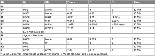
The laser printer was included in the round robin to demonstrate the problems encountered by manufacturers of products that cause flicker. The IEC 61000-3-3 limit for Pst is 0.65. In looking at the data in Table 3, we see that the printer meets the requirement when measured with four of the flickermeters and does not meet the requirement with the remaining six (shaded). If the manufacturer used one of the six (shaded) flickermeter systems in an attempt to qualify his product for the market, the printer would need to be redesigned to meet the Pst requirement.

In evaluating the data summarized in Table 4, we need to know some of the parameters. From Reference 4, we learn that “Dmax” should be the maximum voltage drop that occurs during a test cycle; “Dt” should be the differential between two successive half cycle RMS voltage values; and “Dc” should be the steady-state voltage drop after the EUT stabilizes. Additionally, Dt was reported as a time by some, voltage and percent by others. What is required by the standard?

CONCLUSION
Based on the results of these tests, we are faced with one of two problems: Either the flickermeters do not meet the new standards or the new standards have not improved the measurement accuracy.
REFERENCES
[1] IEC61000-3-2 Edition 2.1 (2001-10) Limits for harmonic current emissions (equipment input current < 16 A per phase) with rated current
[2] IEC61000-3-3 Consolidated Edition 1.1 Limitation of voltage changes, voltage fluctuations and flicker in public low-voltage supply systems, for equipment
[3] IEC61000-4-15 Consolidated edition 1.1 (2003-02) Electromagnetic compatibility (EMC) – Part 4: Testing and measurement techniques – Section 15: Flickermeter – Functional and design specifications.
[4] Mathieu van den Bergh, Harmonics And Flicker Requirements And Instrumentation, CONFORMITY AUGUST 2004.
[5] Mathieu van den Bergh, John Woodgate; Avoiding problems with harmonic current and voltage-change testing according to EN/IEC 61000-3-2 & EN/IEC 61000-3-3; Compliance-club.com Harmonics And Flicker Requirements And Instrumentation, CONFORMITY AUGUST 2004.
FOOTNOTES
(1) The European Union requires compliance to this standard.
(2) Calibration is traceable to NPL, calibrated 16 February 2004.


